
From Oscilloscope to Signal Generator… It’s just incredible how many things you can do with Red Pitaya. This time we used it as a Gain/Phase Analyser.
Gain/Phase Analyser
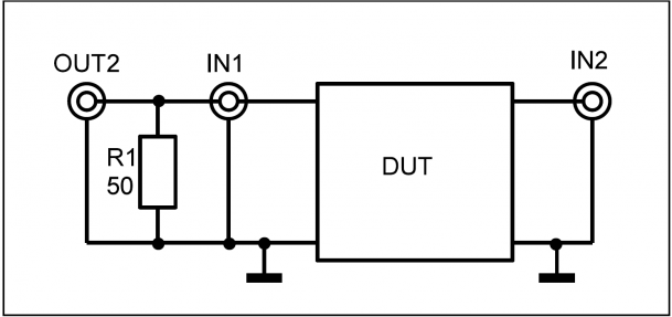
Using one Resistor R1 for proper loading of the signal generator the RedPitaya can be used as a gain/phase analyser to measure gain and phase in the frequency range from 1 kHz to 50 MHz of twoport devices as shown in the following figure:
The signal is generated using fpga-awg signal-generator functionality. The input voltage and output voltage of the ”Device Under Test DUT” are captured with 16384 samples using the fpga-osc osciloscope-trace-capture functionality. Since both voltages are sampled synchronously the phase between the two voltages can be computed. Amplitude and phase of each trace are evaluated by a ”Least Squares” estimation.
The following picture shows the gain (upper red trace) and phase (lower blue trace) of a low-pass filter built with an op-amp. (Upper blue trace shows DUT input voltage.)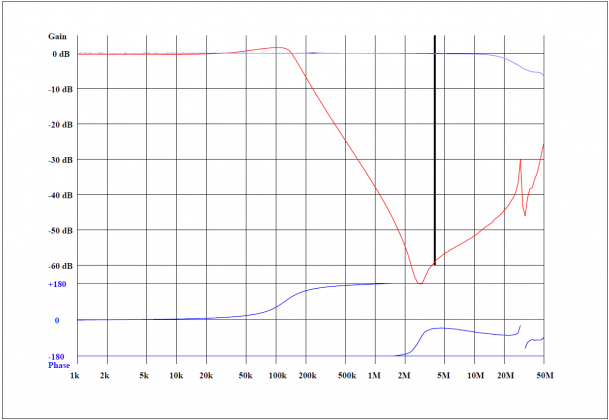
The following picture shows the phase and gain of a 10.7 MHz quartz crystal filter using a 100 kHz sweep span. A dynamic range of 50 to 60dB seems attainable using the RedPitaya.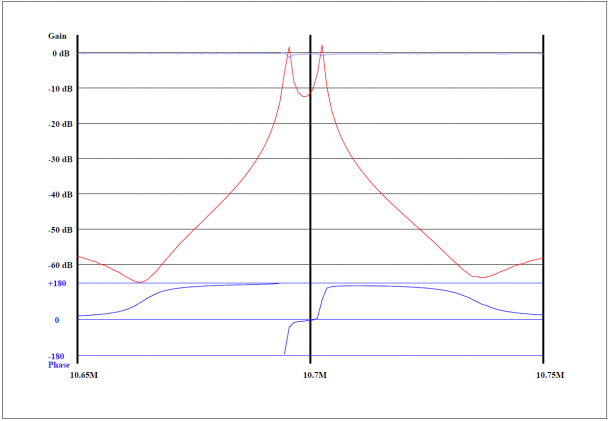
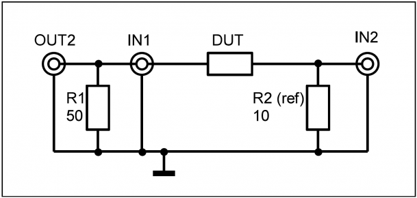
Impedance Analyser
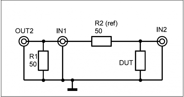
Using R1 for proper loading and R2 as a shunt for current measurement, the impedance of a device DUT can be measured using the RedPitaya in the range from
1 kHz to 50 MHz. Voltage and current for the device are measured in the same way as for the gain/phase analyser.
The various describing parameters of an impedance can be displayed:
Series circuit: Z = R + jX or series inductance Ls or series capacitance Cs
Paralell circuit: Lp Rp and Cp
Also possible is printout of modulus of impedance, angle of impedance and quality factor Q.
The following listing shows the protocol of the measurement of a coil with an inductance of about 850uH with high quality factor.
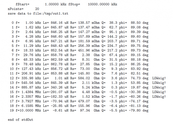
Above 1 MHz the measured inductance is negative, due to the fact that the inductance has its resonance frequency somewhere in the region of 1 MHz. In the region of some hundred kHz the current is too small for a reliable measurement, indicated by ”LOWsig”, since the impedance of the inductor is rather large there. A larger shunt could be used here.
lowdut option:
In order to measure small impedances the ‘lowdut’ option can be used. Cabling is shown in the following diagram. This time the DUT forms the lower component of the voltage divider.
Options for gain/phase/impedance analyser software.
start-frequency and stop-frequency
alternatively: center-frequency and span
log or lin sweep
number of points
value of shunt resistance
parameters to print: Z,X,Rs,Ls,Cs,Rp,Lp,Cp,Q,phi,gain
lowdut option
Software is written in C.


