
Curious if you can build your own radar at home? UCLA student David Zheng did just that — creating a DIY FMCW radar using the Red Pitaya STEMlab 125-14 platform. His kitchen-table experiment evolved into a fully functional radar system that measures distance and velocity — proving that advanced RF engineering is no longer reserved for million-dollar labs. This guide shows how Red Pitaya helps students bridge the gap between theory and hands-on design, empowering them to build sophisticated radars on a student budget.


What Is an FMCW Radar and How Does It Work?
Unlike traditional pulsed radars, which work like sonar by sending out short bursts of energy, a Frequency-Modulated Continuous Wave (FMCW) radar transmits a continuous signal whose frequency steadily sweeps up and down.
This continuous sweep creates a unique timestamp for each moment. When a signal bounces back from an object, its frequency no longer matches the signal being transmitted at that instant. This frequency difference, called the beat frequency, directly reveals how far away the object is.
Why Sweep the Frequency?
When the radar signal reflects off a target, the time delay turns into a measurable beat frequency:
Beat Frequency = (2 × Range × Bandwidth) ÷ (Speed of Light × Sweep Time)
For example, David’s design sweeps linearly from 2.4 to 2.5 GHz (a 100 MHz bandwidth). Each kilohertz of beat frequency translates to about 1.5 meters of distance, providing precise and repeatable range measurements.
How Does FMCW Radar Measure Velocity?
The Doppler effect — the same phenomenon behind a passing siren’s changing pitch — adds speed measurement to FMCW radar. When a target moves, the frequency shifts slightly due to its motion. By analyzing multiple sweeps, the system separates the Doppler shift from the range information, allowing you to measure distance and speed simultaneously.
Why Use Red Pitaya for DIY Radar Projects?
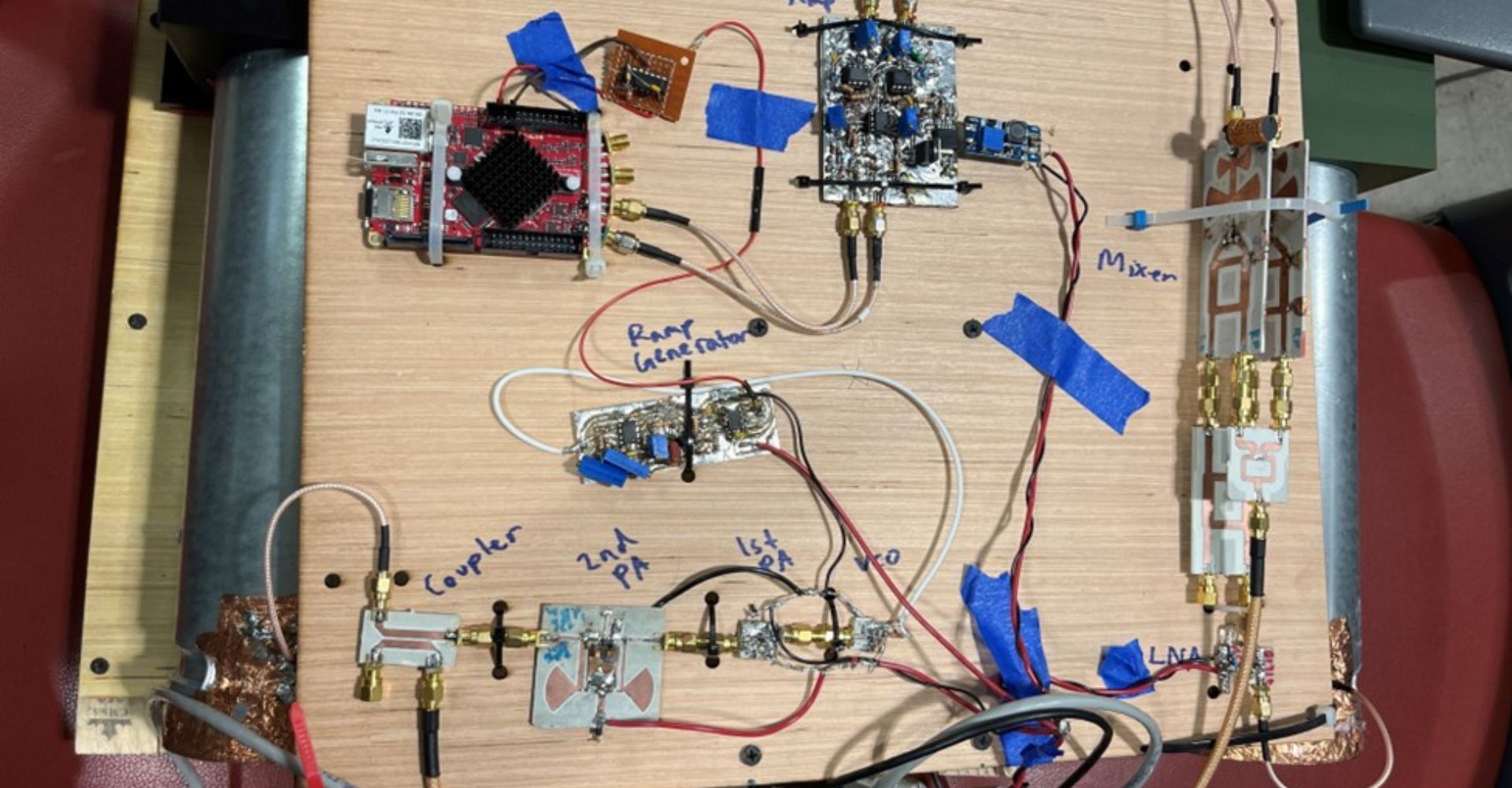
When David Zheng started building his DIY FMCW radar, he didn’t have access to expensive lab equipment. Instead, he used the Red Pitaya STEMlab 125-14 — an open-source measurement and signal processing platform that students and hobbyists can actually afford.
Red Pitaya bridges the gap between theoretical RF engineering and practical hardware design. With its 125 Msps ADC, FPGA, and built-in ARM processor, it lets students digitize high-frequency signals, run real-time processing, and control the entire radar system — all on a single board.
Key System Specs and Tools
Here’s what made David’s DIY FMCW radar project possible with Red Pitaya:
-
Operating Frequency: 2.4–2.5 GHz
-
Sweep Rate: 1 kHz
-
Transmit Power: 26 dBm (400 mW)
-
ADC Sampling Rate: 125 Msps (14-bit resolution)
-
Core Capabilities: Simultaneous distance and velocity measurement
All this came together on a student budget, using off-the-shelf parts and open-source signal processing code — no multi-million-dollar RF lab required.
Why This Matters for Students
This approach proves that advanced RF experimentation isn’t locked behind institutional walls anymore. With accessible hardware like Red Pitaya and clear online resources, any motivated student can design, build, and test sophisticated radar systems — right at a workbench or even a kitchen table.
How to Build a DIY FMCW Radar: A Student’s Step-by-Step Journey
David Zheng’s project is more than theory — it’s a practical roadmap for anyone wanting to build their own DIY FMCW radar using Red Pitaya.
Here’s how he did it, step by step:
Step 1 — Transmitter: Creating the Sweep
At the heart of the radar is a Voltage-Controlled Oscillator (VCO), sweeping frequencies between 2.4–2.5 GHz. This band sits in the ISM range — avoiding regulatory headaches and ensuring easy parts sourcing.
To boost the VCO’s weak output, David designed a multi-stage amplifier chain. Careful impedance matching ensured stable performance and protected components from reflections — a must in RF design.
Step 2 — Generating the Sawtooth
A stable sawtooth waveform controls the VCO sweep. Any nonlinearity here directly affects distance accuracy. David used a 1 kHz repetition rate — fast enough for real-time measurement but slow enough for clear data capture.


Step 3 — Receiver: Extracting the Signal
A directional coupler splits the signal: most goes to the antenna, while a precise portion feeds the IQ mixer. This mixer combines the incoming reflected signal with the reference to produce the beat frequency, which carries the distance and velocity data.
Weak return signals required two stages of low-noise amplification to boost the echo without burying it in noise. This preserved the radar’s range and sensitivity — all within a simple, student-friendly design.
Step 4 — Antenna Design: Why It Matters
David learned that a poorly designed antenna can ruin an entire radar. His clever cantenna (a waveguide made from a metal can) offered high gain and strong directionality — key for focusing the radar’s beam.
Step 5 — Signal Processing: Where Red Pitaya Shines
Red Pitaya digitizes the analog beat frequency using its 125 Msps ADC. Data then runs through a smart two-stage decimation pipeline:
-
Stage 1: CIC filtering cuts data volume with minimal CPU cost.
-
Stage 2: FIR filtering compensates for any roll-off, preserving signal fidelity.
Finally, the Fast Fourier Transform (FFT) extracts distance and velocity by converting the time-domain signal into clear, usable target data.

What Challenges Did He Face?
-
Impedance matching: Every GHz connection is a potential failure point.
-
Thermal drift: Component performance shifts with temperature — he learned to design with tolerances.
-
EMI: The 2.4 GHz band is crowded — proper shielding and filtering were vital.
Lessons for Every DIY Radar Builder
-
Start simple: Validate small subsystems before full integration.
-
Test early, test often: Catch problems before they multiply.
-
Document everything: Debugging is easier when you know what worked and when.
Conclusion: Why DIY FMCW Radar Projects Matter
David Zheng’s DIY FMCW radar project is more than a student experiment — it’s proof that advanced RF engineering can be done on a student budget with the right tools. Using Red Pitaya and clever design choices, he built a system that performs measurements once reserved for expensive labs.
Key Takeaways
- Accessibility: Affordable tools like Red Pitaya open radar design to anyone.
- Hands-On Learning: Real builds teach more than simulations ever can.
- Scalable: This project can evolve — from 2.4 GHz to 24 GHz bands, adding MIMO, or exploring new waveforms.
- Community: Sharing open designs helps the next wave of students learn faster and aim higher.
Inspired? Get started with your own DIY FMCW radar. Use Red Pitaya as your testbed, experiment safely, and share what you learn.
“When advanced tools become affordable, innovation explodes. The only question is: what will you build next?”
Project by: David Zheng, UCLA
Presented at: IEEE at UCLA Projects Showcase 2023
Platform: Red Pitaya STEMlab 125-14
About the Author: David Zheng is a student at UCLA who presented this project at the IEEE at UCLA Projects Showcase 2023. His work demonstrates the potential for student innovation when provided with accessible, high-performance tools like Red Pitaya
Resources and References
Project Documentation:
Red Pitaya Resources:


