

Radars have become standard tools we can find in all sorts of object detection and distance measurement applications for our day-to-day business. Nevertheless, building a homemade Frequency-Modulated Continuous Wave (FMCW) radar from scratch, even with the help of a Red Pitaya board, should by no means be considered a minor feat. Still, that´s exactly what UCLA’s David Zheng managed to do.
Here's his presentation at IEEE at UCLA's Projects Showcase 2023.
FMCW radars consist of an emitting antenna that sends a frequency-modulated signal which is subsequently reflected by an object and captured by a receiver antenna. The most commonly used methods of frequency modulation apply sinusoidal and sawtooth-shaped signals, both of which have their own particular advantages for specific applications. The schematic signal reflection principle that is seen with a sawtooth-shaped signal—indicating time delay Dt, frequency shift Df (proportional to the distance between radar and object), and Doppler frequency fD—is shown below in Figure 1. Not only can performing FFT on the measured frequencies provide us with information on the distance at which the object is detected, but its velocity can also be calculated via 2D FFT using data from multiple sweeps.
%20and%20reflected%20(green)%20signals.png?width=602&height=358&name=Emitted%20(red)%20and%20reflected%20(green)%20signals.png)
Figure 1: Emitted (red) and reflected (green) signals (source: https://www.radartutorial.eu/02.basics/Frequency%20Modulated%20Continuous%20Wave%20Radar.en.html)
The block diagram Zheng used for his radar system is shown in Figure 2 below. A voltage-controlled oscillator, fed with an analog sawtooth wave, generates the transmitter signal in the range of 2.4-2.5 GHz with a 1 kHz sweep rate, which is then amplified in multiple stages to reach the required 26 dBm (400 mW) power. On the receiver side, the IQ mixer captures part of the power amplifier signal via a 15 dB coupler and two amplifiers for improved SNR performance. Finally, at the end of the line, the Red Pitaya unit´s ADC lies waiting to digitalize the measurement information for post-processing. The 125 Msps output of the STEMlab was initially downsampled by a factor of 32 (to ~4 Msps) by a Cascaded Integrator-Comb (CIC) filter, with an additional step to 1 Msps, performed by a Finite Impulse Response (FIR) filter to correct for any amplitude errors introduced by the CIC filter.
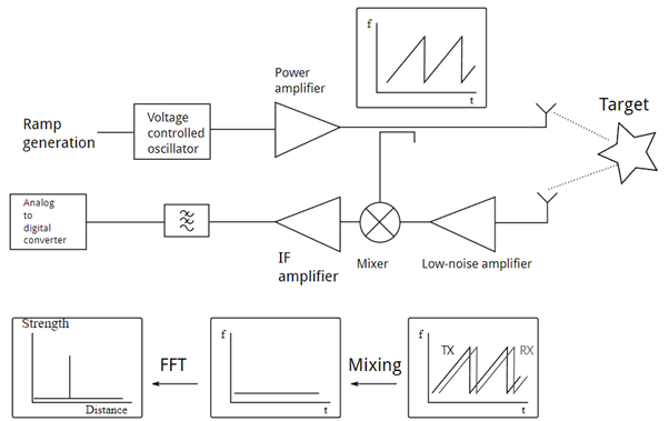
Figure 2: FMCW radar system block diagram (source: https://hforsten.com/third-version-of-homemade-6-ghz-fmcw-radar.html)
On the hardware side, the tricky part of this kind of experiment is often the antenna. Not just the design, but also the execution, since bad coupling can ruin the setup’s performance. A schematic of the cantenna design Zheng used is shown in Figure 3. For his experiment, a 4-inch (~10 cm) diameter pipe was produced, with a 4-to-6-inch diameter drain pipe reducer on the end for a further gain increase.
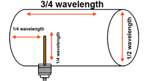
Figure 3: Cantenna-type antenna: schematic design
Launching a “kitchen table” experiment always requires a fair amount of courage, although courage alone offers no guarantee of a good result. Low-budget projects in particular also require a lot of knowledge, creativity, and a keen eye for detail. Unsurprisingly, the people who understand the utility of Red Pitaya’s versatile FPGA boards have exactly these qualities.
Click here to access the full article.


