
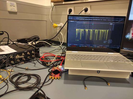
I am Saeid Behjati, a PhD student at Leiden University developing a new Scanning Tunnelling Microscope (STM) as a part of my PhD program. I have developed mechanical parts as well as some analog circuits for this project.
I will explain the basic working principle of an STM so that you can understand my project better. In the figure below you can see a simple schematic of the instrument:
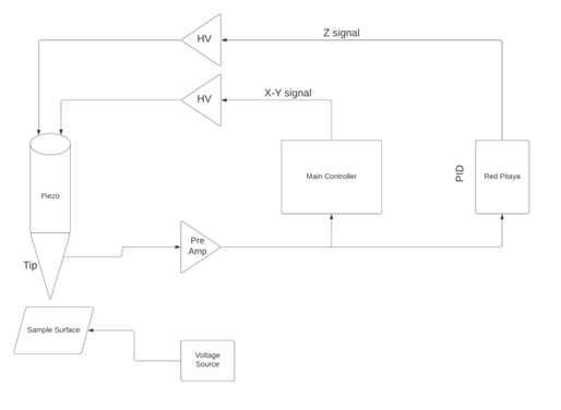
Figure 1 Simple schematic of the instrument
On the bottom left side, we can see the sample is connected to a voltage source called the tunneling voltage. A small gap exists between the tip and sample in the nanometer range, so the tunneling current can run between the tip and sample. The tip, which is atomically sharp, is connected to a high gain amplifier (labelled Pre-Amp in the schematic) to convert the tunneling current into voltage. The output of the pre-amp is connected to the Red Pitaya board, as well as the main controller. The output of the Red Pitaya board is connected to a high voltage amplifier to drive the piezo tube in the Z direction. There are also two outputs from the main controller, which are connected to another high voltage amplifier to drive the piezo in the X and Y directions.
The controller will apply different waveforms to the piezo, and the piezo will scan the sample surface in the X and Y directions.
Let’s focus on the part of the schematic where I used the Rep Pitaya board. The magnitude of the tunneling current is an exponential function of one over the distance between the tip and sample. By adding a logarithmic amplifier, we can eliminate the exponential behavior. So the input of the Red Pitaya board is a linear function of the output. It is essential to have a constant tunneling distance, because we need a constant distance between the tip and the sample to record the topography of the sample with atomic resolution. To be able to do that, we need to have a closed feedback loop to control the height of the tip by applying the proper voltage in the Z direction. It is well known that we have four critical parameters in a standard PID controller. The DC offset voltage, proportional gain, integral gain, and derivative gain. To increase the development speed, I decided to use an already available code for the PID controller, which can be found here.
The standard version of the PID works well, but I have some ideas to improve it further, like adding a logarithmic converter in the FPGA to remove the analog logarithmic amplifier. I am also planning to use the 14-bit version of the Red Pitaya board to improve the performance/resolution of the PID in the future.


