Red Pitaya CAN! Can you?
-
Posted by
 Red Pitaya Technical Editorial Team
, November 21, 2024

We are happy to announce that the Red Pitaya board now features a CAN bus, in addition to the already available I2C, SPI, and UART communication interfaces!
What is a CAN bus?
The Controller Area Network (CAN) bus is a communication system used primarily in automobiles, but also in other systems, to allow communication between different Electronic Control Units (ECUs) without the need for a host computer. Each ECU controls a different system in the car. Brakes, airbags, cruise control, the engine and much more besides all have an ECU, and with over 70 different ECUs in a car, a reliable source of communication that can handle critical transfers is required.
This problem was addressed by Robert Bosch GmbH in 1983 with the introduction of the CAN bus. A two-wire bus consisting of CAN high (yellow) and CAN low (green) differential wires that connect all ECUs (also called nodes) into a single chain. Each node can communicate with any other node, with a priority system that gives way to communication from nodes with a higher priority (CAN ID), forcing other nodes to wait their turn.


Image 1: ECU
Each ECU consists of three elements:
- Central Processing Unit – processes the received data and passes data to the CAN controller for transmission.
- CAN controller – generates and reads CAN frames.
- CAN transceiver – converts the data stream between the CAN controller and the CAN bus levels.
The main advantages of CAN are:
- Simplicity – The CAN bus replaces the old point-to-point analog communication with a standard cable that allows communication among all connected nodes.
- Scalability – New nodes can easily be added at one end of the chain.
- Accessibility – All communication is accessible from any point on the bus.
- Robustness – CAN uses a differential signal and includes error handling protocols to minimize errors caused by electromagnetic interference.
- Efficiency – Nodes with lower CAN ID numbers have communication priority over nodes with higher ID numbers. This allows critical information to reach its destination immediately, while other systems wait their turn on the bus.
Over the years, the need for faster communication has driven the development of CAN. The most widely used version is CAN 2.0 (also known as high-speed CAN), with flexible data-rate CAN (CAN FD) and CAN XL on the rise.
How can you use the CAN bus on a Red Pitaya board?
With that explanation out of the way, we can finally focus on the main topic: How do we connect a Red Pitaya board to the CAN bus?
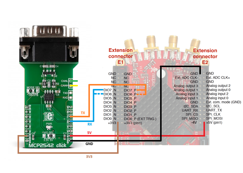
Compared to the ECU, the Red Pitaya board acts as a combination of CPU and CAN controller, decoding CAN frames, extracting and processing the information, and encoding CAN frames according to the specifications set by the user. An external CAN transceiver is required to successfully connect to the CAN bus. Here we will connect the MCP2542 Click Board, which is also used in the following examples.
- Connect the MCP2542 to the Red Pitaya board:
- Connect the TX pin of the CAN transceiver to the CAN0 RX pin on the Red Pitaya.
- Connect the RX pin of the CAN transceiver to the CAN0 TX pin on the Red Pitaya.
- Connect the power and ground pins.
- Use a DE9 cable to connect the transceiver to an external CAN bus or to another MPC2542 click board.

Image 2: MCP2542 connected to a Red Pitaya
- Select the desired command interface (SCPI or API commands).
- Follow the instructions for setting up the environment for the selected interface.
- Open the CAN communication example and copy the code into your favorite editor.
- Execute the example.
With Red Pitaya we can connect up to two different CAN buses. We can replace the functionality of the digital pins DIO7_N and DIO7_P with the CAN0 interface and DIO6_P and DIO6_N with the CAN1 interface. We can change the functionality by using the "CAN:FPGA ON" SCPI command (or its C/Python API equivalent). The CAN interface is connected to the external CAN transceiver with the RX pin connected to the TX port and the TX pin connected to the RX port.

Image 3: CAN data frame structure
The versatility of the CAN commands allows us to go far beyond the existing CAN2.0 specifications. We can achieve speeds of up to 10 Mb/s, a maximum data payload size of 8 bytes, and the ability to extend data frames and send remote transmission requests.
Of course, the versatility does not end here. The open source code invites us to add our own ideas to improve the existing functionality and to adapt it to the needs of our projects.
Example code
You can find examples of CAN communication code here:
Sources
You can read more about the CAN bus here:
About the Red Pitaya Team
The Red Pitaya Technical Editorial Team is a cross-functional group of technical communicators and product specialists. By synthesizing insights from our hardware developers and global research partners, we provide verified, high-value content that bridges the gap between open-source innovation and industrial-grade precision.
Our mission is to make advanced instrumentation accessible to engineers, researchers, and educators worldwide.


