
Modern quantum optics experiments require a broad range of laser frequencies, including for applications outside the highly specialized laboratories with ideal conditions, increasing the demands regarding mechanical robustness of the optical setup. These requirements are already met by laser sources for a restricted wavelength range, but not necessarily for second harmonic generation (SHG) setups which allow extending the range of specific wavelengths.
When light passes through a nonlinear medium, it is possible to generate SHG light at twice the value of the initial frequency. In order to increase the efficiency of c.w. light in a β-BaB2O4 (BBO) crystal, an enhancement cavity is built around the nonlinear crystal.
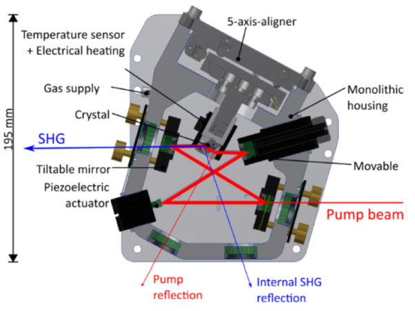
An experimental setup, described by S. Hannig, J. Mielke, J. A. Fenske, M. Misera, N. Beev, C. Ospelkaus, and P. O. Schmidt in the Review of Scientific Instruments, uses a bow-tie power enhancement cavity for critical SHG with a Brewster-cut BBO nonlinear crystal, delivering up to 2,500 times more SHG output power than is possible in single pass configuration. The cavity geometry is suitable for all UV wavelengths, reachable with BBO. Interferometrically stable cavity length is paramount in order to assure constant output power. This is done, using a mobile mirror, mounted on a piezoelectric actuator, as shown in Fig. 1.
Figure 1: Schematic cross-section of the experimental bow-tie SHG cavity, where a lightweight mirror on a piezoelectric actuator is used to lock the cavity length
Traditionally, the mobile mirror position is controlled by an analog PI feedback loop. Fast digital FPGAs now make it possible to perform fast PID-control, using universally applicable, flexible, and easily reconfigurable off-the-shelf components. When referring to this type of instrument, involving portable, solid, and precise components, one easily comes across a Red Pitaya. In this experimental setup, the STEMlab 125-14 unit was integrated to guarantee the precise positioning of the mirror and stable SHG output power. Fig. 2 shows how the STEMlab is connected to the different components of the setup.
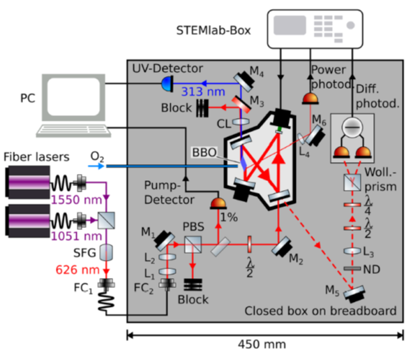
Figure 2: Schematic overview of the setup for 313 nm generation, with the STEMlab 125-14, integrated as fast PID-controller
The error signal, generated by the differential photodiode is fed into a real-time digital PI control algorithm on the STEMlab unit (STEMlab comes with a standard PID control application, where the D-parameter was set to 0). The benefit of running the algorithm directly on the device is a considerable reduction in latency. A user-interface touchscreen and rotary encoder were added in order to allow the unit to work in standalone mode. The setting of the PID parameters, as well as a series of additional functions, was done using Linux. These additional functions include digital output voltage limitation, automatic integrator reset, and a sample-and-hold mode, and can run in parallel with the PID algorithm, without affecting its real-time performance.
The fundamental purpose of this experimental enhancement cavity was to demonstrate the long-term stability and portability of the equipment. To do so, three main tests were carried out. During the first one, SHG output power was monitored for 130 hours. The result showed power fluctuations around 3% rms on a time scale of several hours, and 1% rms when we rescale SHG power to that of the pump light (see Fig. 3).
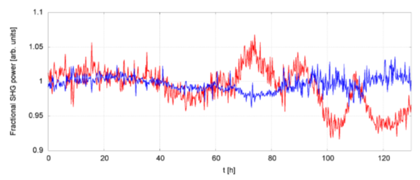
Figure 3: Long-term SHG output power measurement. Red: measured SHG power, where "1" equals 186 mW. Blue: SHG normalized to PL power squared as a measure of conversion efficiency.
The second test involved SHG stability measurement against a 1 g vertical acceleration, where the output power fluctuated around 10% during the acceleration and recovered initial power after the acceleration stopped. The final test was also related to the mechanical solidity of the equipment, this time focusing on transportability. The setup was submitted to a 30-minute shaker test at 3.020 grms to simulate road transportation conditions. While the SHG output power dropped to about 60% after the shaker process, initial power could be restored by realigning the optical components of the cavity. This indicates that the main improvements of the design are needed on the mechanical stability of the input coupling optics, but that the concept is valid.
In short, this experiment shows that, when it comes to taking traditional laboratory applications into the field, you can always count on the reliability, accuracy, and portability of Red Pitaya units.
This blog post was written based on the article by Hannig, J. Mielke, J. A. Fenske, M. Misera, N. Beev, C. Ospelkaus, and P. O. Schmidt. The full article is available here.


