
With the release of the new Red Pitaya Click Shields, some of you may have noticed that the Click Shield synchronization functionality overlaps with the X-Channel System. So what’s the difference?
The Red Pitaya X-Channel System consists of a primary device and multiple secondary devices connected in a daisy chain via the SATA cables. The primary device is a low noise version of the STEMlab 125-14, which shares its clock and trigger signals with all secondary devices (which are also low noise secondary versions of the STEMlab 125-14). This enables synchronous data acquisition and operation across all units in the chain.

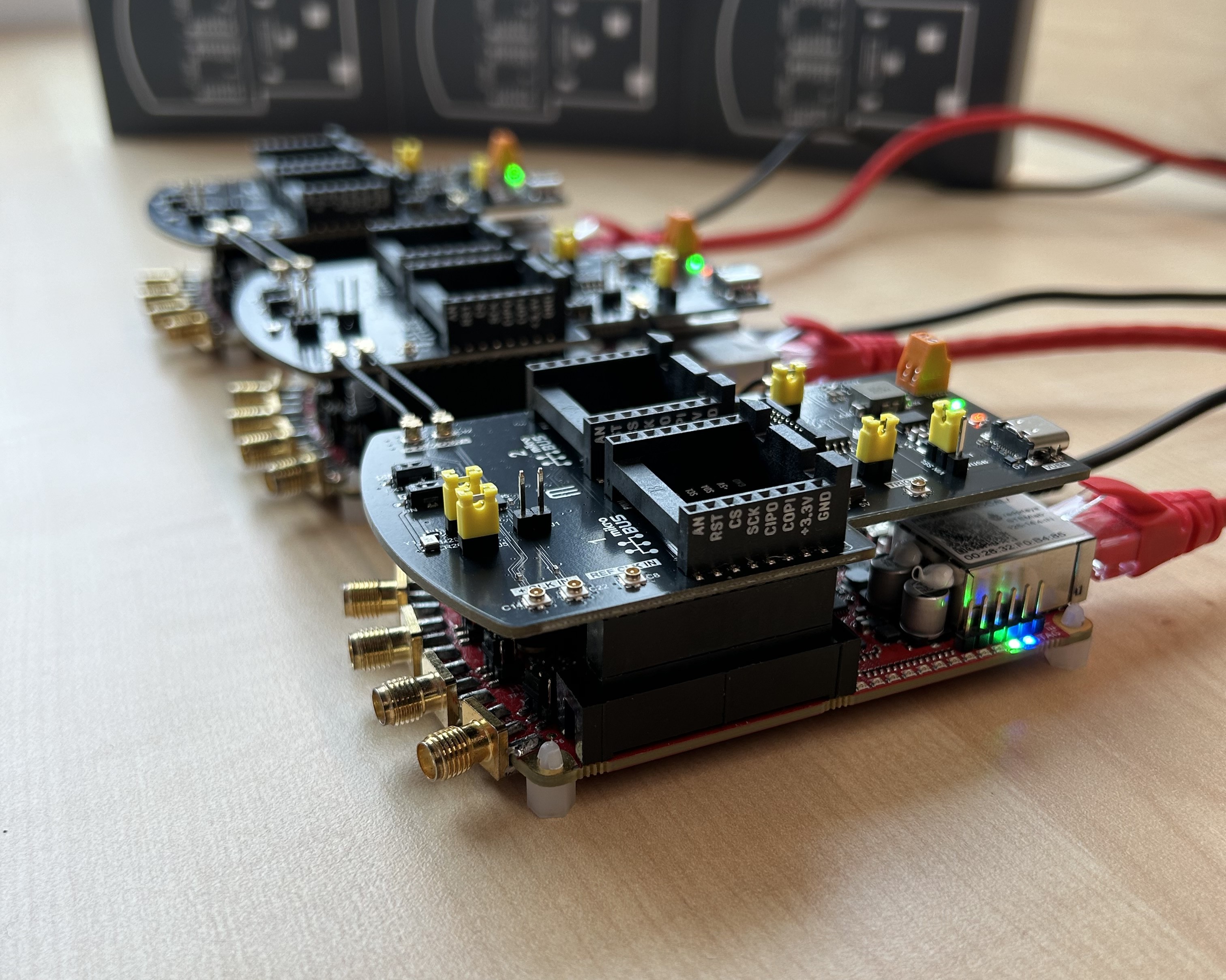
The Red Pitaya Click Shield is an expansion for any Red Pitaya board, and can be used not only to connect two MIRKOE Click Boards and extend the power range of Red Pitaya, but also to synchronize multiple Red Pitaya boards via U.FL cables.

Both systems synchronize multiple Red Pitaya boards and provide access to multiple high-speed analog inputs and outputs. Data from all synchronized boards can be captured simultaneously to a file on a computer via the streaming application and the desktop client, which controls the parameters of the application. The advantage of daisy-chaining Red Pitayas is that there is no data speed bottleneck on the primary unit, as each unit transmits data over an Ethernet cable.
For the purposes of this comparison, we will only focus on synchronization options and pinout accessibility, which is important for some projects.
The main hardware difference is that Red Pitaya Click Shield synchronization is more flexible, as it allows synchronization between several different Red Pitaya boards. All units in the Click Shield synchronization chain must be external clock versions (STEMlab 125-14 external clock, SDRlab 122-16 external clock) or have the ability to receive an external clock (STEMlab 125-14 4-input and all future models of Red Pitaya boards). In addition, the Click Shield synchronization chain can be synchronized by external clock and trigger sources via the U.FL connectors on the Click Shields or the oscillator on the primary Click Shield, while the X-Channel System can only share the clock of the primary device.


Click Shields also have less clock signal delay and skew because each Click Shield has a clock buffer that keeps the clock signal edges sharp no matter how many units are synchronized. The shared clock of the X-Channel System passes through the FPGA of each secondary board, so the distortion increases with the number of boards being synchronized. However, the difference is negligible with fewer units in a chain.
In terms of pinout accessibility, the X-Channel is superior as it allows full pinout access to the expansion connectors on each board. While the Click Shields provide flexibility in handling even 5V digital logic and other digital communication interface buses (other than the CAN bus) through the microBUS connectors, they limit access to the digital GPIOs to a maximum of 10 digital pins (three digital pins on each of the two microBUS connectors and access to eight digital pins through the logic analyzer connector) out of 16 or 22, depending on the board model. Click Shields also prevent the addition of custom hardware to the Red Pitaya. The same applies to the slow analog inputs and outputs, where only two of the inputs and none of the outputs are accessible through the Click Shield.
Overall, we recommend using the Red Pitaya Click Shields for:
- High frequency applications (to capture data up to 125 or 122.88 Msps, depending on the Red Pitaya board model)
- Synchronization of the Red Pitaya chain to an external clock
- Synchronization of different Red Pitaya board models
And we recommend the X-Channel System for:
- Mid to low frequency applications (up to 100 ksps)
- Full access to Red Pitaya pinout on extension connectors
- Reduced noise on fast analog outputs is required (lock-in amplifiers and similar applications)


All information in this article is summarized in the table below:
|
|
X-Channel System |
Click Shields |
|
Clock & Sampling rate |
||
|
Recommended sampling rate |
up to 100 ksps |
up to 125 Msps |
|
Shared clock signal |
Primary device clock |
Click Shield Oscillator or an external clock |
|
Clock signal delays |
Slightly higher delay per unit (signal through each FPGA)1 |
1x Clock buffer per unit - ZL40213 |
|
Trigger signal delays |
Slightly higher delay per unit (signal through each FPGA)1 |
1x Trigger buffer per unit - 74FCT38072DCGI |
|
Pinout |
||
|
GPIO access |
Full access2 |
Max 10 digital pins3 |
|
Slow analog access |
Full access (4/4) |
Max 2 pins (2/4)3 |
|
Digital communication pins |
1x UART, 1x SPI, 1x I2C, 1x CAN |
2x UART, 2x SPI, 2xI2C (no CAN)3 |
|
Units |
||
|
Compatible Red Pitaya board models |
Primary - STEMlab 125-14 LN
Secondary - STEMlab 125-14 LN Secondary
|
All the same or a combination of: STEMlab 125-14 external clock SDRlab 122-16 external clock STEMlab 125-14 4-Input |
|
Switching between external and internal clock |
No |
Yes4 |
|
Aluminum case compatibility |
No |
Yes |
1 Exact measurements will be provided here in the future
2 Depending on the board model there can be either 16, 19, or 22 GPIO pins. See the comparison table for more information.
3 Via the microBUS connectors.
4 STEMlab 125-14 4-input and future HW board redesigns
Information on the differences between the two systems can be found in our documentation here.


