
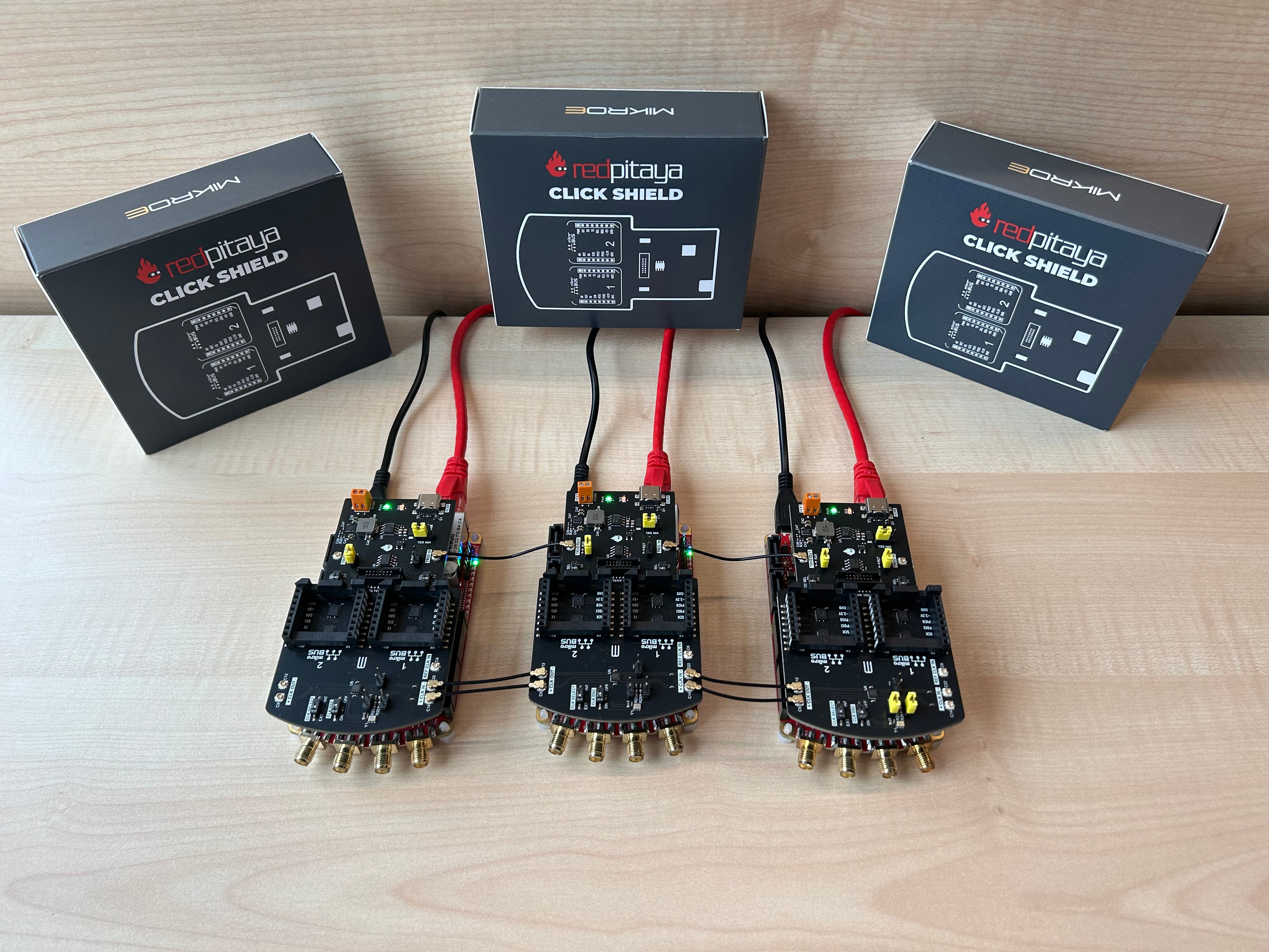
The second Click Shield article in the series is here, and this time we’ll take a look at the synchronization of multiple Red Pitayas using Red Pitaya Click Shields. When talking about synchronization, we’re referring to clock and trigger synchronization of multiple devices, which means all the devices in the chain share the same clock signal ensuring all the important processes like data acquisition and generation happen at exactly the same moment.
Here's a simple, everyday example of synchronization: Imagine arriving at the bus stop at 06:58 and checking the bus schedule to see when the next bus arrives. The schedule says the first bus arrives at 07:00 and then every 20 minutes. If the bus is synchronized with the schedule, it'll arrive exactly on time at 07:00, but if not then it might arrive five minutes late, or even worse, five minutes early, which means we’ve already missed it and might be late for work. Now let’s imagine three desynchronized buses on the same line, each still arriving in exact intervals of 20 minutes, but one is always three minutes early, the second is always seven minutes late, and the final one is always on time. However, if the buses are fully synchronized with the schedule then they always arrive exactly on time – at 07:00, 07:20, and 07:40. But enough about buses and the worry of being late for work, and let's get back to the Click Shields.
To simplify the situation we’ll assume we want to synchronize three Red Pitaya boards, although the following instructions can easily be upscaled for complex projects.
What do we need?
- First of all, we need three Red Pitaya units compatible with the synchronization feature. These can be any combination of STEMlab 125-14 External Clock, STEMlab 125-14 4-Input, and SDRlab 122-16 External Clock, including their low-noise variations.
- Three Red Pitaya Click Shields (one for each unit).
- Six to nine U.FL cables (depending on whether we plan on using the oscillator on the Click Shield as our external clock source, or a separate external clock). U.FL cables are miniature surface-mount RF coaxial connectors with a characteristic impedance of 50 ohms that are designed for high-frequency performance (DC – 6 GHz). (Read more on U.FL cables here.
- Finally, all units must have Red Pitaya OS 2.00-23 or higher installed.
OK, now that we have everything ready, let’s dive in.
How does the synchronization work?
One of the main abilities of a Red Pitaya Click Shield is the synchronization of multiple Red Pitaya units. As U.FL cables are used for clock and trigger synchronization, other external clock devices can also be included in the chain. The connection provides minimal clock signal delay between multiple Red Pitaya units, as there is only a single ZL40213 LVDS clock fanout buffer between two units.
In this article, we present two possible synchronization configurations. The first uses the onboard Click Shield oscillator as the clock source and the primary Red Pitaya unit’s trigger signal as the external trigger source. The second version uses both an external clock source and an external trigger source.
Oscillator
We establish the following connections with U.FL cables between the primary board and secondary board, place the corresponding jumpers, and change the switch positions on each Click Shield as explained below.
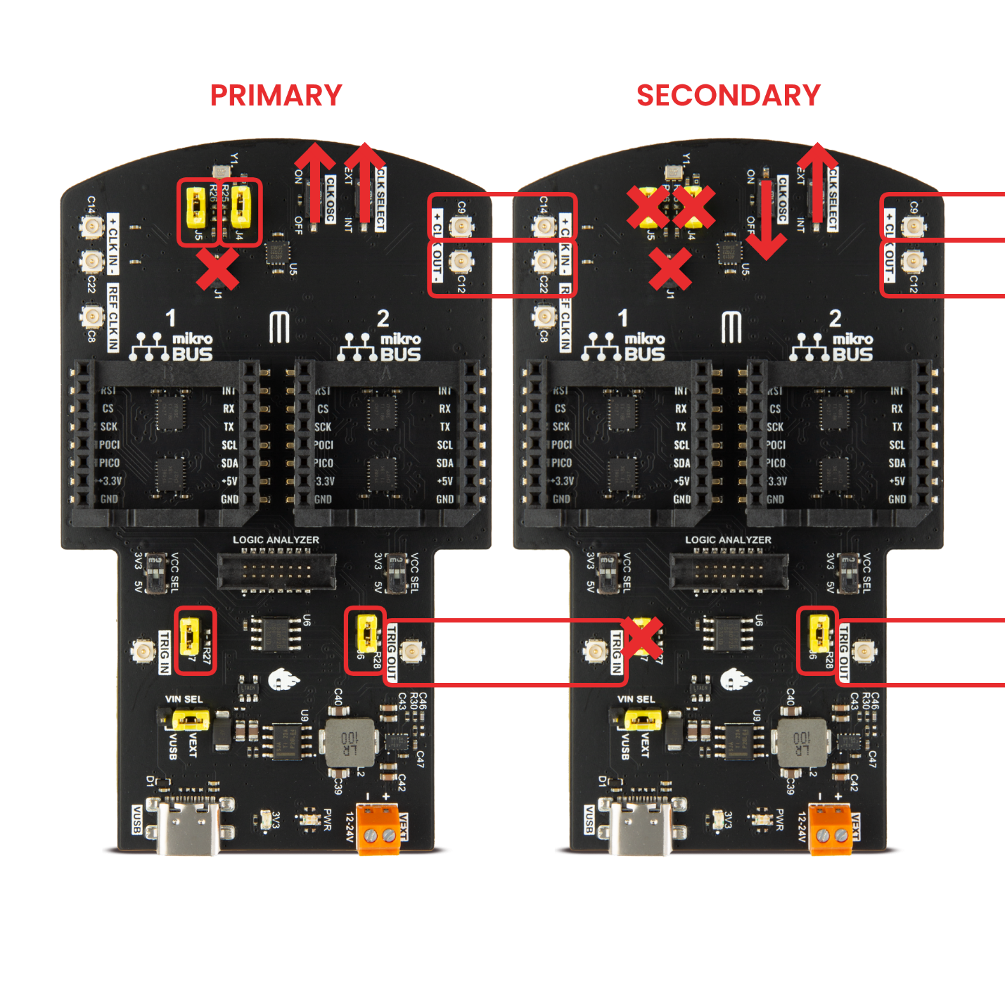
Primary board:
- Connect the oscillator to the clock transmission line:
- Jumpers J4 (CLK +) and J5 (CLK -) connect the primary Click Shield oscillator to the external clock transmission line.
- Establish the trigger signal connection:
- Jumpers J6 (Ext trig source) and J7 (Ext trig sink) connect the primary trigger signal to the external trigger transmission line.
- Adjust the oscillator and clock settings:
- Jumper J1 is used only for the single-line clock signal, so leave it disconnected.
- Set the CLK OSC switch to the ON position to turn on the oscillator.
- Set the CLK SELECT switch to the EXT position to ensure the 4-Input boards are in the correct mode of operation. Other board models are not affected by this change.
Secondary boards:
- Disable the secondary oscillators:
- For each secondary board, disconnect jumpers J4 and J5 to prevent multiple clock sources from interfering with the primary clock.
- Establish the external trigger reception:
- Connect jumper J6 on each secondary board to enable external trigger reception and synchronize it with the trigger transmission line.
- Finalize the clock selection:
- Ensure the CLK OSC switch is set to the OFF position on each secondary board to deactivate their onboard oscillators.
- Set the CLK SELECT switch to the EXT position to ensure the 4-Input boards are in the proper operation mode. Other board models are not affected by this change.
External clock source
We establish the following connections with U.FL cables between the primary board and secondary board and place the corresponding jumpers on each Click Shield into the shown positions. Here all boards can be treated as secondary, as no unit is the source of either clock or trigger signals.

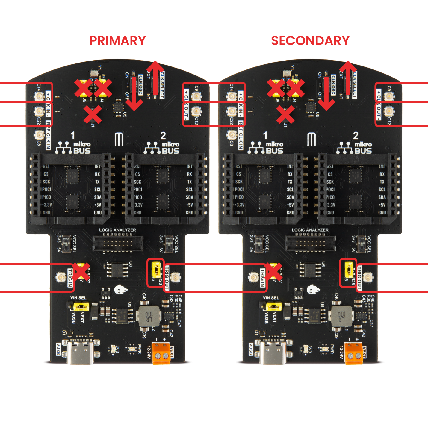
Primary and Secondary boards:
- Prepare all the boards for external clock connection:
- Disconnect jumpers J4 and J5 on every board to disconnect the onboard oscillators and prevent interference with the external clock.
- Enable the external trigger sink:
- For every board, connect jumper J6. This enables all boards to receive external trigger signals.
- Disable the onboard trigger sources:
- Ensure jumper J7 is disconnected on all boards to disconnect the external trigger output pins from the external trigger transmission line.
- Select the external clock and disable the onboard oscillators:
- Set the CLK OSC switch to OFF on all boards to turn off the onboard oscillators.
- Set the CLK SELECT switch to the EXT position to ensure the 4-Input boards are in the proper operation mode. Other board models are not affected by this change.
Other configurations
The instructions set out above can easily be mixed and matched if we want some other combination of clock and trigger signals. For example, perhaps we have an external clock but want the primary device to transmit its trigger signal to all the other devices.
Code example
The final step is to configure the software. Here is a quick illustration of how to arrange the external trigger source for the primary board for the oscillator example given above:
Want to learn more?
Then check this link.


