
When thinking of nuclear fusion experiments, you don’t immediately expect to find pocket-sized components in charge of data acquisition and monitoring. And yet, the ITER Neutral Beam Test Facility, located in Padova (Italy), discovered the added value Red Pitaya STEMlab boards could bring to their SPIDER experiment.
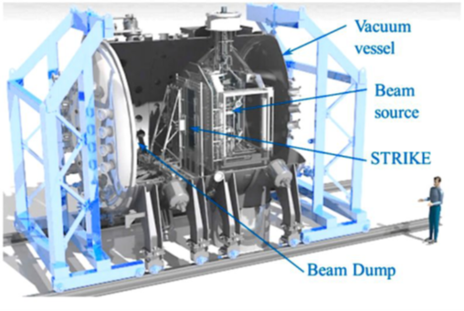
Figure 1: Schematic view of the SPIDER experiment
SPIDER is the first large experimental device for Neutral Beam Injection (NBI), serving as a study test bench to improve the neutral beam design for ITER, the experimental fusion reactor under construction in the south of France. The elements installed in this experiment are subject to severe conditions, with strong potential gradients between components and high currents flowing through the source and vessel when breakdown events occur.
To explain why STEMlab 125-14 boards were chosen for data acquisition and conversion tasks in this project, we need to understand the main strengths of SoC FPGAs. The most important task of DAQ components in the SPIDER experiment is interacting with the processing unit. Flexible logic design enables greater ease of data transfer to high-level tools for archiving (such as MDSplus) or for performing runtime analyses. Moreover, relatively small-sized components make it possible to embed these systems close to the sensors, which can lead to a solution that integrates several different diagnostics systems into a single unsupervised model. The innate flexibility of SoC boards, capable of embedding full OS such as GNU Linux, combined with their small size, automatically brings these components into the picture, and the Red Pitaya units are textbook examples of compact, highly flexible FPGAs.
Because of these characteristics, the STEMlab 125-14 boards were adopted in the SPIDER experiment. A previous design for high-speed, event-driven DAQ, using an expensive commercial device, did not meet all the requirements of the project. In an updated version, the Red Pitaya FPGAs were implemented to solve this problem, using their built-in event-triggering capacity, based on input signal characteristics such as level and gradient. The Red Pitaya event-driven DAQ was also used to provide streamed spectral RF source measurements, where the boards receive trigger sequences (up to 200 Hz) that generate frames where data are sampled at frequencies up to 125 MHz. These data are then streamed to the network via the embedded Zynq CPU.
A total of 12 STEMlab boards were integrated in the SPIDER experiment diagnostics systems – as can be seen in the schematic diagram in Fig. 2, below – and divided into four functional categories.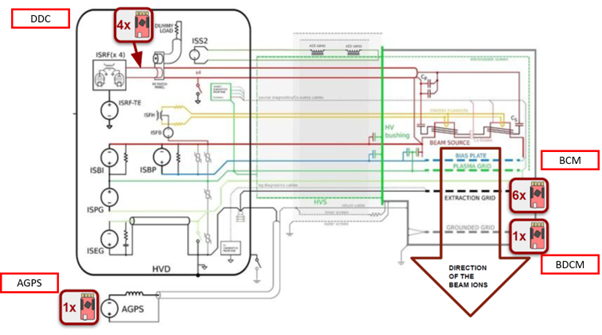
Figure 2: Red Pitaya units integrated in the SPIDER experiment diagnostics, divided into four categories: DDC, BCM, BDCM, AGPS
- DDC (Dual Directional Couplers): Transducers, used for power measurement, providing two analog output signals (forward and reflected voltage) that are connected to the analog inputs of the STEMlab 125-14, as can be seen in Fig. 3, below. The four Red Pitaya units that are used for this goal are synchronized via an optical signal connected to the first unit, with the other three units linked by means of IN/OUT fiber optic connections.
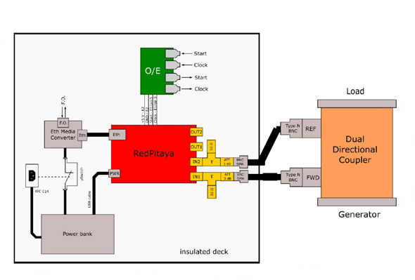
Figure 3: STEMlab connected to the DDC
- BCM (Beamlet Current Measurement): Five current sensors were mounted on the active apertures of extraction beamlets. Each sensor consists of a LEM sensor (closed-loop current transducer, able to extract the DC component for slow dynamics), a current transformer, and an electrostatic plate, working as a free-positive-ions repellant which removes the current component, attracted by the electric field on the grid output, but that is not part of the beam. Six Red Pitaya units monitor a total of 10 measurement signals (two per current sensor), as shown in Fig. 4, below.
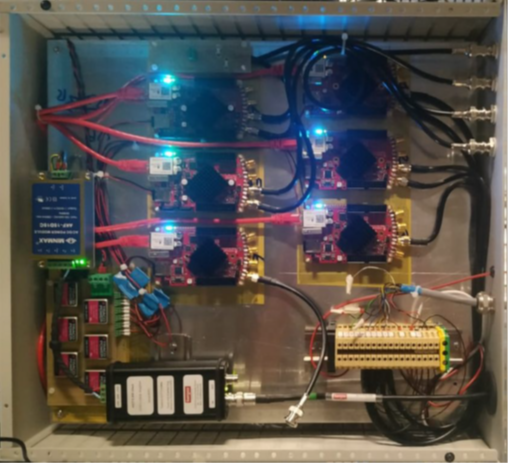
Figure 4: Red Pitaya units reading current measurement signals from five BCMs
- BDCM (Beam Dump Current Measurement): The beam dump component mainly absorbs the beam power, extracted from the RF plasma. The beam dump was also designed to measure the total beam current flowing through the dumper panels. Figure 5, below, shows how the STEMlab is connected and delivers readable beam dump current information.
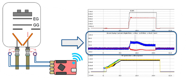
Figure 5: BDCM with STEMlab connected
- AGPS (Acceleration Grid Power Supply): This 96 kV HV power supply provides 8 MW power to the beam source for all internal acceleration grids. The Red Pitaya board allows analysis of the low-voltage ripple effect.
The STEMlab 125-14 units were successfully integrated in the SPIDER experiment, thanks to their ease-of-implementation, the capacity of their full-fledged Linux environment to autonomously perform complex operations, affordable price, and compact and careful design, which can be adapted to many applications. The user’s satisfaction with the developed solutions is such that the Red Pitaya units are also scheduled to be used in similar projects in the future, such as MITICA and RFX-mod2, the upgrade of the RFX-mod fusion experiment, currently under construction in the same lab.
Read more about directional couplers here and more about bean current measures here.


