

Nowadays, ultrasound (US) imaging is a widely used technique in medical applications. Acoustic signal bursts, at frequency ranges well above the human hearing limit, are reflected by the different tissues with different intensities, and capturing these reflected signals makes it possible to create an image of virtually any organ or tissue within the human body. This technology is obviously similar to other imaging techniques, such as traditional radiography or CT scan, but has the added advantages of lower cost and safer, radiation-free, operation.
The usual, handheld US techniques produce 2D pictures, where the operator needs to move the probe around the area under investigation in order to mentally create a 3D image for real-time diagnosis. This makes the operation extremely dependent on the operator’s skills and experience, and, as such, more sensitive to human error. Exact probe positioning, combined with the proper data acquisition tools, can be used to digitally create a 3D image which can be stored for later in-depth study. These systems, combining robot systems with US probes and DAQ equipment, already exist but are generally rather expensive. In his 2020 Master thesis, Joshua Teye (TU Delft) describes how he developed a similar system with low-cost components, resulting in a functional unit for 3D US imaging.
Bearing in mind that, to achieve this, the combined data of both the US system and the robotic arm needed to be generated, acquired and processed, and that the budget was limited, it is no surprise that the developer turned to Red Pitaya to constitute the core element for his project. A STEMlab 125-14 unit, increasingly more popular thanks to its 14-bit resolution, was integrated in the Wearable Ultrasound Platform (or WUP), developed by Philips Research, together with an Arduino Teensy microcontroller development board and a Philips PCB (fig. 1).
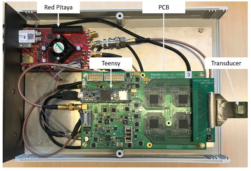 Figure 1: Wearable Ultrasound Platform, including the Red Pitaya STEMlab 125-14
Within this assembly, the Red Pitaya work horse is in charge of generating the acoustic pulses via one of its analog outputs and sending them to a 32-channel US probe. Rather than a classic piezoelectric probe, where a crystal transforms an electric signal into mechanical vibrations and vice versa, a Capacitive Micro-machined Ultrasound Transducer (CMUT) was used for reasons of cost reduction. These probes convert flexural vibration of electrostatically charged plates into capacitance variations, able to produce or pick up acoustic signals. The STEMlab ADC then converts the reflected echo into digital data for image processing (Fig. 2). At maximum sampling frequency (125 MS/s), taking into account the 16k buffer and the soundwave velocity in soft tissues, this results in a maximum scanning depth around 10 cm.
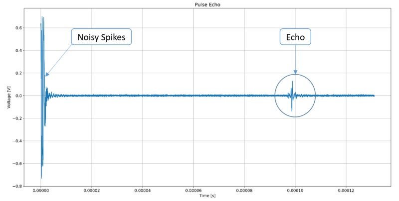 Figure 2: Acoustic pulse and reflected echo signal, generated and captured by the STEMlab in- and outputs
In parallel, a Linux-based Robotic Operating System (ROS) was also installed on the Red Pitaya, allowing to control the full functionality of the WUP system. This ROS provides, at any given time, the precise location and orientation of the robotic arm, making it possible to precisely assemble the different 2D images into a 3D shape.
A number of tests were performed to verify the outcome of the project. The images below show 3D-scans of 2 phantom objects, demonstrating that relatively low-end components can be ideal substitutes for expensive devices in many applications when budgets are limited. Red Pitaya, with a proven track record in smaller projects for educational purposes, is a perfect example of this philosophy.
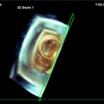
Figure 3: 3D-scan of phantom object 1
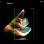 Figure 4: 3D-scan of phantom object 1
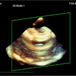 Figure 5: 3D-scan of phantom object 2
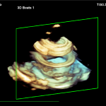 Figure 6: 3D-scan of phantom object 2
Full article available here: https://repository.tudelft.nl/islandora/object/uuid:ced96a5f-8174-473b-a20d-298804db712b/datastream/OBJ/download


