
Imaging techniques have become everyday instruments in the medical world, providing us with valuable information regarding our physical condition and possible health problems. Despite their impressive performance, MRI, radiography and ultrasound systems do have some drawbacks when it comes to portability, or the energy they deposit in our tissues, potentially causing long-term damage.
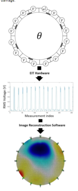 Fig. 1 Schematic overview of the EIT imaging process
The basic concept of Electrical Impedance Tomography (EIT) involves injecting tiny currents into the body through a series of electrodes, and measuring the related voltages. The recorded variations in tissue conductivity can then be used to create an image of body parts, similar to MRI scans (see schematic diagram of the process in Fig. 1), and detect possible anomalies. Since the current and voltage values are too low to cause any tissue damage, EIT can avoid one of the disadvantages of more traditional imaging techniques. Although some devices are already commercially available, it is still a growing technology with considerable margin for improvement.
In an effort to tackle the second issue with traditional imaging techniques, i.e., the bulky size of the instruments, J. Schluchter published his master’s thesis “A 16-Channel Electrical Impedance Tomography System Using the Red Pitaya” for the University of California (San Diego). This project actually represents a further development of an 8-channel EIT project by Z. Xu e.a, where this technology had already been explored (also including a Red Pitaya unit). By increasing the number of channels to 16, Schluchter managed to develop and build a setup with greater accuracy.
The experimental setup was built around the multitasker under the FPGAs, Red Pitaya’s STEMlab 125-14 unit. As can be seen in Figs. 2 and 3, a voltage-controlled current source (VCCS) converts a voltage signal, generated by the STEMlab analog output, into a constant current. Multiplexer units (MUXs) then allow switching current and voltage connections between the 16 electrodes on the setup, without having to perform any physical de- or re-connection work. The electrodes were installed around a basic tank, a 3D-resin printed 112 mm diameter cylinder with a height of 25 mm, filled with a saturated brine solution to provide a conductive environment for the experiment.
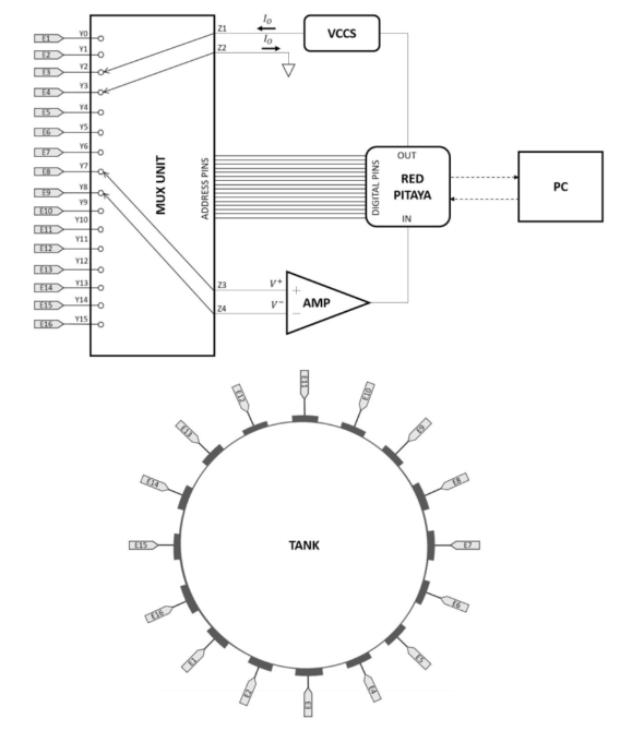 Fig. 2 Schematic diagram of the experimental setup, with the STEMlab unit at the heart of the connections
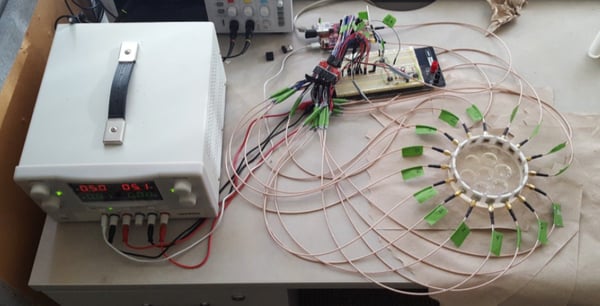 Figure 3 Photograph of the setup
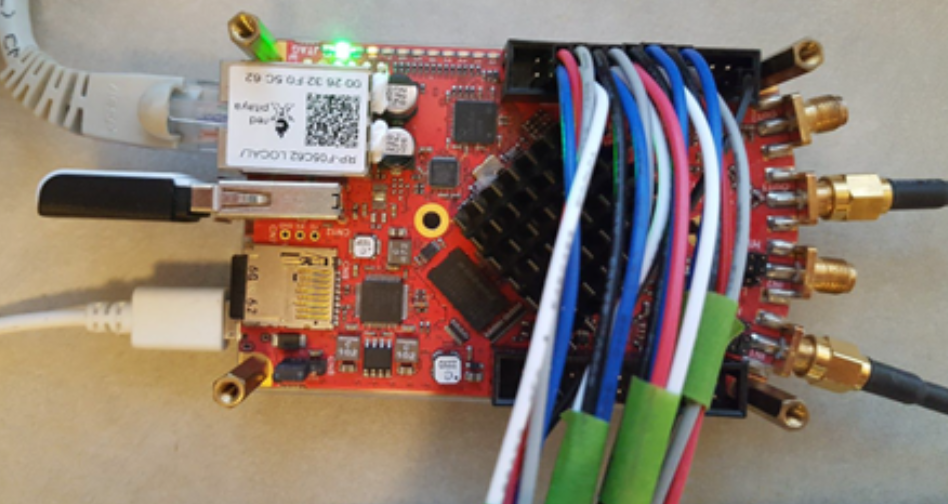
Not only was the Red Pitaya unit MATlab-programmed to produce the output voltage signal, it was also in charge of acquiring the data of the measurement signals and sending the digitalized information to a computer for post-processing. Figure 4 shows a detail of the connected STEMlab, with the analog input and output visible on the right-hand side, and the digital data connection at the top of the picture.
 Fig. 4 Detail of the connected STEMlab unit
Two electrode configurations were tested (pin vs. plate electrodes), of which the pin version gave the most conclusive results. Figure 5 shows the actual test setup, with the corresponding image after post-processing, shown in Figure 6.
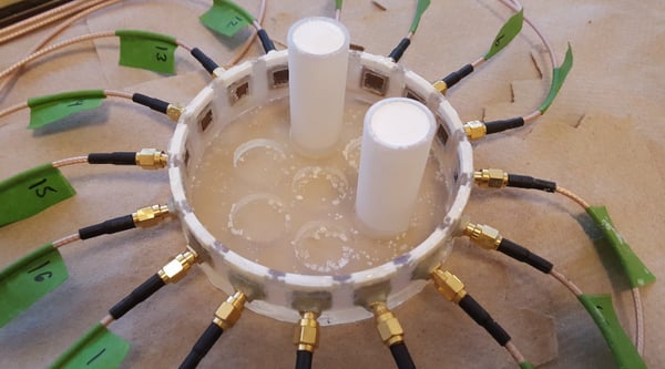 Fig. 5 Photograph of the test setup
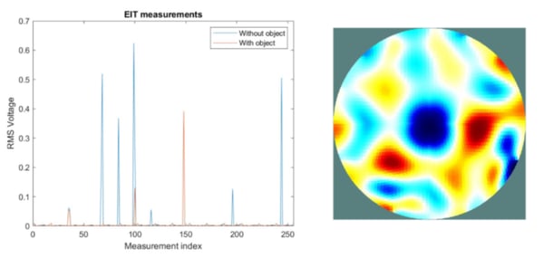 Fig. 6 Resulting image from the test setup
Further experiments using the point-electrode setup provided the following series of simulations (right) and reconstructed images (left) of test objects in eight different positions (Figure 7). An identical test with plate electrodes led to inconclusive results.
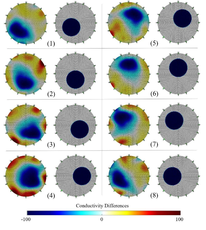 Fig. 7 Point-electrode tank object reconstruction in 8 sample positions
The conclusion of Schluchter’s thesis is that, besides the visual correspondence between reality and the produced images, the signal-to-noise ratio of this experiment is also quite satisfactory. With 34 dB, it is comparable to some commercial systems, although high-end devices reach values around 80 dB, with the drawback that these systems are expensive and not portable. Obviously there is still quite some room for improvement: fine-tuning the design, increasing the number of electrodes, etc. Nevertheless, this experiment demonstrates that a low-cost setup can work very well and give encouraging results, which is exactly what the Red Pitaya units stand for: small packages with a lot of power for modest budgets.
Full article available here: https://escholarship.org/uc/item/7969r8kb


