
The race for the development of autonomous driving technology is on. Obviously, this technology needs to be foolproof and 100% safe, which demands ultraprecise instruments that guarantee optimum performance, not only in the sheltered environment of an R&D lab, but in all kinds of environmental conditions.
Advanced Driver Assistance Systems (or ADAS) constitute an important block of devices for autonomous vehicles, and include a wide range of technologies: ultrasound sensors, radars, cameras and LiDAR (Light Detection and Ranging) systems. In a paper, published in 2021 under the title “Improvement of Accuracy and Precision of the LiDAR System Working in High Background Light Conditions” (https://www.mdpi.com/2079-9292/11/1/45), Thanh-Tuan Nguyen, Ching-Hwa Cheng, Don-Gey Liu and Minh-Hai Le describe how they integrated a Red Pitaya STEMLab 125-14 unit in an optical distance measurement system for improved behavior in realistic background light conditions.
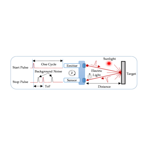
LiDAR systems use near-IR light to detect objects, measure distances and build 3D point cloud maps, based on the Time-of-Flight (ToF) principle, where a short laser pulse is emitted and reflected by the object we want to detect. The time measured between emission and reception gives a precise indication of the distance between target and detector. Since we´re dealing with an optical system, it goes without saying that external light conditions, both artificial and natural, generate a considerable noise signal, interfering with the measurement and potentially leading to anomalous results. The goal of this project was to filter out interference and produce a system with increased reliability for all background light conditions, both indoors and outdoors.
Figure 1 shows the ToF-measurement principle (including background noise signals), along with a schematic view of the detector with emitter-receiver and the reflecting object.
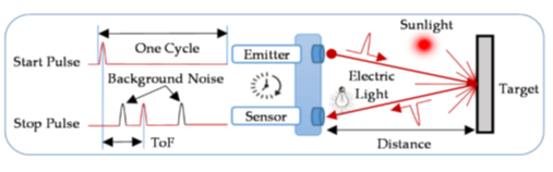 Picture 1: Time-of-flight detection principle
The hardware of the system is built using four main blocks, as can be seen in Fig. 2.: 1) emitter laser diode, 2) receiver sensor including a Single-Photon Avalanche Diode (SPAD), 3) embedded signal processing platform with the STEMLab 125-14, and 4) PC for remote control.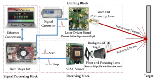
Figure 2: Main building blocks of a LiDAR system
The emitter unit consists of an EPC9126 laser driver that simultaneously sends a start pulse to the ML101J25 laser diode and signal processing block. The 650 nm wavelength laser beam, with a rather high divergence angle (17°), is focused into a narrow beam (Ø2.35), as can be seen in the schematic view of Fig. 3.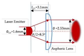
Figure 3: emitter unit optical diagram
The receiver basically performs the reverse process, with a focus lens generating a narrow beam for the 25 mm2 active diameter of the SPAD sensor (see Fig. 4). This unit already includes a 650 nm bandpass filter to eliminate the bulk of background light noise.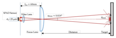
Figure 4 Receiver unit optical diagram
Despite the presence of this filter, multiple noise pulses still find their way to the detector, which can be seen in Fig. 5, where a comparison is presented between dark lab conditions (a), lab conditions with strong background light (b), and outdoor conditions in broad daylight (c).
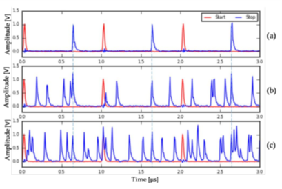
Figure 5: Comparative study of received pulses in different environmental conditions
Safe object detection for autonomous vehicles is clearly impossible in these conditions. The most effective way of filtering the received signal, beyond the capacity of the physical filter, is by post-processing the received pulses to identify which ones can be attributed to the emitted light. This is where the Red Pitaya unit comes in. The STEMLab 125-14 uses its two fast Linux-operated ADCs and a Python signal processing program to digitize start (emission) and stop (reception) signals, determining the ToF, and then calculates the detector-object distance.
For this type several estimation methods can be used. This project explored two main methods, peak detection and cross-relation. The latter estimates time delay, based on the maximum correlation of the emitted and received signals in full waveform, and is widely used when high accuracy is required in high-noise conditions. A third exercise was performed with a parabolic interpolation algorithm – the CCP method – for improved resolution and accuracy, by fitting the parabolic function to the three maximum points of the correction function.
After a series of measurements in the three previously mentioned conditions (i: dark lab; ii: lab with high background light; iii: outdoor with high background light) for object distances ranging from 10 to 90 m, with the peak detection, cross-correlation (CC), and CC with parabolic interpolation (CCP) methods. The comparative results are plotted in the graph in Fig. 6, showing the clearly superior performance of the CCP method, with high and consistent precision over the entire distance range (around 7.4 cm).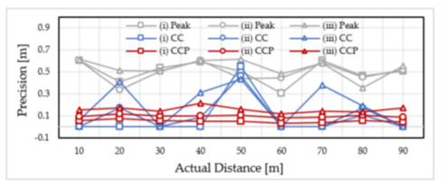
Figure 6: Precision for peak detection, CC and CCP methods with different background light conditions
When comparing these results with similar studies using different setups, we find one case where a 500 MSps sampling frequency produces a 30 cm precision, against the 7.4 cm in this project. A second example sampled at 1 GSps reached a precision that was only three times better for a frequency which was eight times higher.
Given the consistent and satisfactory results of the project, using the CCP estimation method, and with relatively limited means, it is safe to conclude that whenever you need high performance at a budget then integrating Red Pitaya units in your setup is the logical choice. Devices delivering higher sampling frequencies are not necessarily a guarantee of better performance, and generally come with a higher price tag.


