Paramount in this case is not the practical application — you can buy an FM radio cheaply after all — but rather the principles applied. A normal broadcast FM signal (stereo plus R(B)DS) with a bandwidth of 400 kHz calls for digital processing of corresponding efficiency and capability. Red Pitaya measures up to this challenge admirably.
To call Red Pitaya nothing more than a USB oscilloscope would be a shallow understatement. In the introductory article in Elektor we explained how this programmable open-source instrumentation platform could also be deployed as a signal generator, spectrum analyzer, oscilloscope, PID controller and much more besides. Numerous programs for doing this are available free.
The concept
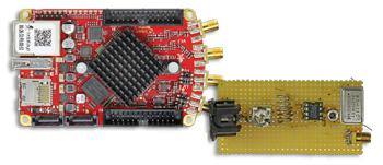
Red Pitaya can digitize signals up to around 50 MHz. For this reason a simple front-end is required to convert the broadcast band between 88 and 108 MHz down to the region between 22 and 42 MHz. An NE612 is deployed as mixer, using the 66 MHz crystal local oscillator LO1. The signal from the ADC in Red Pitaya is sampled at 125 MS/s and fed to the FPGA. It’s in the FPGA that the first stage of our FM receiver is achieved, mixing down to baseband (zero IF) and the filtering.
Inside the FPGA
The mixing process in the FPGA is carried out using a DDS oscillator, which follows the signal generator provided with Red Pitaya. Instead of passing the output to a D/A converter, this signal is used for mixing within the FPGA. Sine and cosine signals are obtained by read-out from the table, using an offset that corresponds to 90 degrees. This produces a so-called I/Q mixer
FM demodulation
As the pair of IQ signals already contains information on the instantaneous phase of the signal, we can derive the actual phase simply using the C function atan2(Q,I). The current frequency is calculated by establishing the difference between consecutive values. In the process we naturally need to take care that at the transition from π to –π the phase alters only seemingly. After frequency determination we have a low-pass filter.
Final thoughts
A project of this kind is obviously not completed in a single weekend. It’s important to progress in stages, checking the functionality of each individual block (mixers, filters, rate reduction and control circuits) one at a time. When you do this, it is worth outputting test signals from the FPGA or the C software using the D/A converter and evaluating these with the ‘scope. In this respect the process for a software-based project resembles classic hardware development.
Read and/or download full article HERE.
About the Red Pitaya Team
The Red Pitaya Technical Editorial Team is a cross-functional group of technical communicators and product specialists. By synthesizing insights from our hardware developers and global research partners, we provide verified, high-value content that bridges the gap between open-source innovation and industrial-grade precision.
Our mission is to make advanced instrumentation accessible to engineers, researchers, and educators worldwide.