


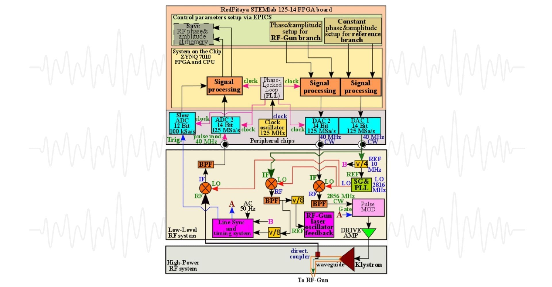
The evolution of FPGA development boards and control electronics over the last two decades has enabled the implementation of FPGA-based Low Level Radio Frequency (LLRF) feedback and feedforward systems for precise control of the accelerating field using high frequency ADCs and DACs in combination with the down-conversion approach.
The LLRF system developed at the KEK LUCX facility for controlling the phase and amplitude of the accelerating field of a normal conductivity multi-bunch linear electron accelerator combines the advantages of two main groups of LLRF system architecture implementations. The system is based on a Red Pitaya STEMlab 125-14 FPGA board and an Agilent E8663B Signal Generator (SG), and it allows control of the RF-gun laser injection phase with 100 fs (RMS) precision. It also provides relative stability of the RF-gun accelerating field phase to the 12-cell Linac field phase of 120 fs (RMS), and it enables synchronization between the Compton laser pulse train and the electron beam of 100 fs (RMS). It is imperative that all systems are stabilized by digital LLRF phase and amplitude inter-pulse feedback in order to eliminate drifts caused by temperature and humidity variations in the accelerator tunnel.
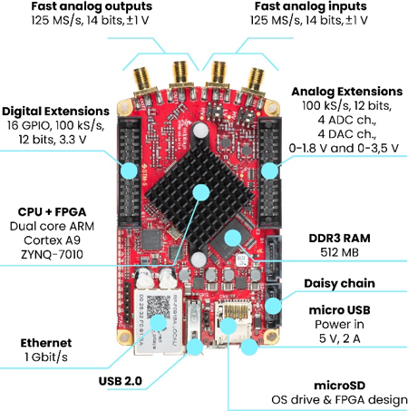
Figure 1: RedPitaya STEMlab 125-14 FPGA board overview.
The novel LLRF system integrates a Red Pitaya board, frequency dividers, an Agilent E8663B SG equipped with a preinstalled conventional 10 MHz PLL, RF-mixers, band-pass filters (BPF), and a pulse modulator, as illustrated in Figure 2. The constant 40 MHz signal generated on DAC 1 is used as a reference to phase-lock the SG (which generates a common 2816 MHz Local Oscillator (LO) signal) with the Red Pitaya, as well as up-mixed to 2856 MHz, filtered with a narrow-band BPF, and frequency divided to get the 8th sub-harmonic of the accelerating frequency. The sub-harmonic is then phase-locked with the RF-Gun laser oscillator feedback and timing system and, in a separate branch, the 10 MHz reference signal by the Line Sync generator, which also removes the AC line instability in the Low-Level RF and High-Power RF systems.
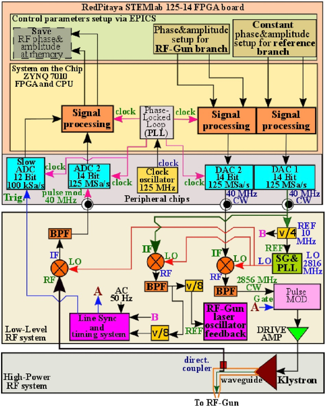
Figure 2: Simplified schematic of KEK LUCX facility RF-Gun LLRF system branch with RedPitaya STEMlab 125-14 FPGA board based LLRF phase&litude control.
The RF-Gun signal is initiated as a (phase and amplitude) controllable 40 MHz CW signal generated on DAC 2 output, which is subsequently up-converted to 2856 MHz, filtered by the BPF, modulated by the 3.125 Hz, 4 µs wide gate signal generated by the LUCX timing system and finally amplified, first to 700 W by the drive amplifier and then to 12 MW by the klystron, which transfers it to the RF-Gun cavity via waveguide system.
The RF-field feedback signal is extracted from the waveguide by the directional coupler, down-converted to 40 MHz with the common LO signal, filtered and fed to the ADC 2 input. The result is then processed to extract the phase and amplitude of the accelerating field and saved to the EPICS PV.
The KEK LUCX facility is equipped with two normal conductive standing-wave accelerating cavities. The LLRF system utilizes two Red Pitaya boards, which are clock-synchronized via SATA cables. The master board controls the RF-Gun accelerating field, while the slave board controls the 12-cell Linac accelerating field and the Compton laser oscillator piezo feedback.
As illustrated in Figure 3, phase stability measurements of all system signals demonstrate that the maximum attainable RF-Gun stability is defined by the phase stability of 357 MHz and 2856 MHz CW signals. The RMS phase noise of the signals is as follows; reference signal injected into the 10 MHz PLL 0.005°, IF noise 0.03°, LO noise 0.048°, RF noise 0.079°, accelerating field 8th sub-harmonic 0.012° or 92 fs.
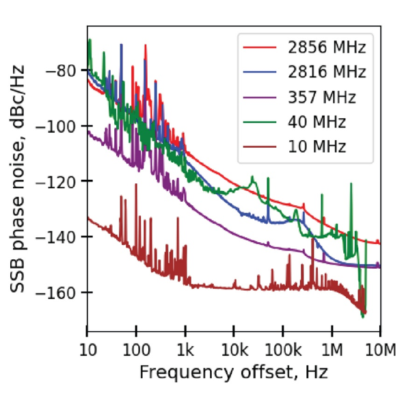
Figure 3: CW signals phase noise map.
Based on:
K. Popov, A. Aryshev, and N. Terunuma, ‘Beam stabilization at KEK LUCX facility by Digital LLRF phase&litude feedforward implementation into RF system’, in 21st Annual Meeting of Particle Accelerator Society of Japan, Yamagata, 2024, Accessed: Apr. 11, 2025. [Online].
Available: https://www.pasj.jp/web_publish/pasj2024/proceedings/PDF/WEP0/WEP077.pdf
Recent Posts
-
-
 September 22, 2026
 -
 September 17, 2026