
Key Takeaways
- Unclonable Physical Fingerprints: Manufacturing variations in output driver strength, parasitics, and clock jitter create sub-microsecond analog imperfections during digital signal transitions. These physical characteristics cannot be copied by reflashing firmware or stealing cryptographic keys.
- Standalone Inference Engine: Leveraging the Xilinx Zynq SoC on the Red Pitaya STEMlab 125-14 Pro Gen 2 allowed the team to execute signal acquisition, feature extraction, and ML classification inside a Docker container directly on the board—eliminating host PCs and benchtop oscilloscopes.
- 99.5% Clone Identification Accuracy: The system achieves 99.5% accuracy in identifying individual identical-model devices and 100% accuracy in detecting device types across 8 embedded development boards in the peer-reviewed baseline paper (USENIX VehicleSec 2026), and has since been extended in ongoing work to a fleet of 9 production automotive ECUs on a commercial vehicle platform.
- High-Precision Feature Extraction: The pipeline extracts 211 time-domain, frequency-domain, and wavelet features from waveforms captured at 125 MS/s with 14-bit ADC resolution, focusing on rise times, slew rates, and ringing behavior.
- Self-Verified Measurement Chain: By looping the Red Pitaya's signal generator back into its input, the team verified that the board introduces less than 0.1% spectral harmonic distortion and 0.0% rise-time error, proving the captured fingerprints belong to the target device, not the instrument.
Two circuit boards. Same manufacturer, same model, same firmware, sending byte-identical messages. One of them is counterfeit.
Nothing in the software can separate them. A cloned device carries valid credentials and looks completely legitimate to every check the system performs.
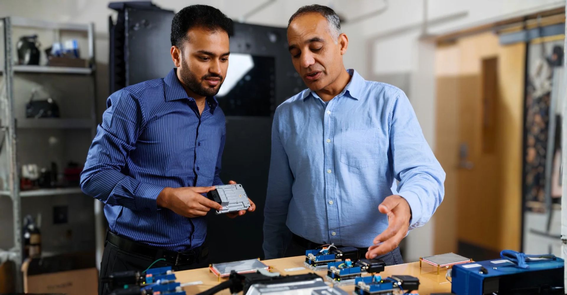
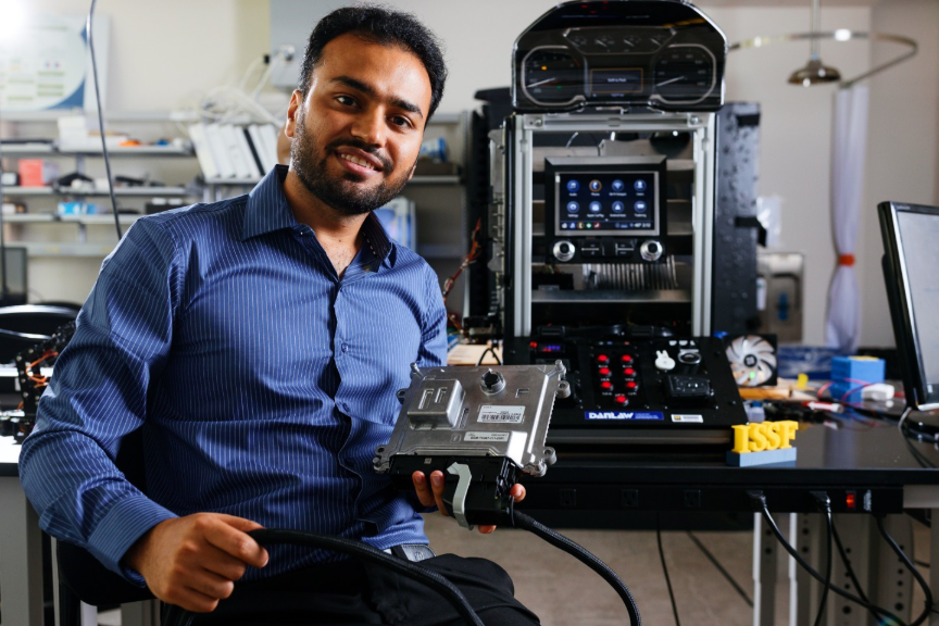
To solve this vulnerability, researchers at the Information Systems, Security, and Forensics (ISSF) Laboratory at the University of Michigan-Dearborn developed a hardware authentication framework that identifies individual embedded devices by analyzing the intrinsic analog shape of their digital switching signals. By leveraging the on-board processing and high-speed data acquisition of the Red Pitaya STEMlab 125-14 PRO Gen 2, the team built an end-to-end, real-time authentication pipeline that eliminates the need for a host PC.
“You can copy firmware, a serial number, or a message. You cannot copy physics.”
The Threat Model: When Cryptography Checks the Wrong Badge
Modern vehicles contain over 100 Electronic Control Units (ECUs) communicating via CAN bus, LIN, and Ethernet. Similarly, industrial cyber-physical systems—from robotic arms on a factory floor to medical equipment—rely on embedded controllers communicating via digital ON/OFF switching signals.
Today’s security frameworks rely heavily on cryptographic authentication (such as SecOC in AUTOSAR). While cryptography effectively verifies message integrity, it cannot detect hardware-level substitution attacks. If an adversary physically replaces a legitimate ECU with an identical-model clone programmed with modified firmware and transferred credentials, the software will accept the impostor as legitimate.
“Cryptography checks the badge. It has no way to check the hand holding it.”
When two devices send identical digital payloads—such as byte-identical messages like 0x1A4—traditional cryptographic checks validate both as authentic because they possess the same firmware and data. However, evaluating physical-layer transients reveals clear structural differences. While a genuine ECU might exhibit a rising edge of 8.2 ns and pass verification, a counterfeit unit with an 11.4 ns rise time is immediately flagged and rejected.
To answer the fundamental question—“Is this the same physical ECU that was originally installed?”—security systems must evaluate properties below the software abstraction layer.,
The Threat Model: When Cryptography Checks the Wrong Badge
Modern vehicles contain over 100 Electronic Control Units (ECUs) communicating via CAN bus, LIN, and Ethernet. Similarly, industrial cyber-physical systems—from robotic arms on a factory floor to medical equipment—rely on embedded controllers communicating via digital ON/OFF switching signals.
Today’s security frameworks rely heavily on cryptographic authentication (such as SecOC in AUTOSAR). While cryptography effectively verifies message integrity, it cannot detect hardware-level substitution attacks. If an adversary physically replaces a legitimate ECU with an identical-model clone programmed with modified firmware and transferred credentials, the software will accept the impostor as legitimate.
“Cryptography checks the badge. It has no way to check the hand holding it.”
When two devices send identical digital payloads—such as byte-identical messages like 0x1A4—traditional cryptographic checks validate both as authentic because they possess the same firmware and data. However, evaluating physical-layer transients reveals clear structural differences. While a genuine ECU might exhibit a rising edge of 8.2 ns and pass verification, a counterfeit unit with an 11.4 ns rise time is immediately flagged and rejected.
To answer the fundamental question—“Is this the same physical ECU that was originally installed?”—security systems must evaluate properties below the software abstraction layer.
Hardware Architecture: Bridging the Acquisition & Deployment Gap
Historically, physical-layer hardware fingerprinting research suffered from a major deployment bottleneck: reliance on bulky laboratory bench oscilloscopes sampling at 2.5 GS/s, tethered to high-performance workstations.
“Published work in this field relied on bench oscilloscopes running at 2.5 GS/s, tethered to a workstation. That is exactly why none of it ever reached a vehicle.”
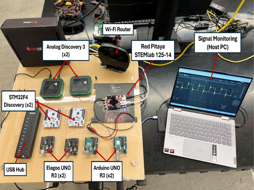
To build a field-deployable system, the UM-Dearborn researchers selected the Red Pitaya STEMlab 125-14 PRO Gen 2 running in high-voltage mode. By organizing the acquisition and processing system around the Red Pitaya's internal hardware architecture, the team created a self-contained pipeline. The board's analog front-end uses dual 14-bit ADCs sampling at 125 MS/s to feed digitized signals into a deep DMA buffer (capable of storing 16,000 to 2,000,000 samples) within the FPGA fabric. From there, data streams directly into the dual-core ARM Cortex-A9 processor running an embedded Linux environment inside a Docker container to perform real-time machine learning inference.
Key Technical Specifications & Selection Factors
- Integrated Compute & Acquisition: The AMD Xilinx Zynq-7010 All Programmable SoC pairs a dual-core ARM processor directly with the FPGA logic and ADCs. This allowed the team to execute signal capture, feature extraction, and machine learning inference directly on the board inside a Docker container, using a host PC during the enrollment phase, but running standalone inference directly on the Red Pitaya.
- 125 MS/s Sample Rate (8 ns Resolution): The transient features live in the first few hundred nanoseconds after a switching edge. At 125 MS/s, the STEMlab captures roughly 190 samples across a typical transient window, providing sufficient resolution to characterize overshoot and ringing dynamics.
- 14-Bit ADC Resolution: Same-model clone devices exhibit millivolt-scale differences. Lower-resolution 12-bit ADCs compress away these critical analog variations.
- Deep DMA Capture: Capturing up to 2 million samples per trigger at 125 MS/s yields a 16-millisecond window, enabling the continuous acquisition of complete automotive CAN frames without dropping samples.
- Synchronized Dual Channels: Automotive CAN is a differential bus (CAN_H and CAN_L). Synchronous dual-channel acquisition allows analysis of individual lines separately as well as the differential signal, revealing driver asymmetry that standard differential receivers cancel out.
- High-Voltage Mode: Enables direct probing of standard logic levels and automotive bus voltages without needing external attenuation circuits that degrade signal fidelity.
Signal Processing & Feature Extraction Pipeline
The authentication system operates across two main operational phases: an Enrollment Phase and an Authentication Phase. During enrollment, target devices generate a 1 MHz PWM stimulus while connected to a host PC monitoring setup. The Red Pitaya STEMlab 125-14 captures a 16,384-sample window per trigger, extracts a 211-dimensional feature vector, and populates the enrollment database with trained models. During the authentication phase, an unknown input device undergoes the exact same capture and extraction steps directly on the Red Pitaya.
The 211-dimensional feature vector combines two complementary extraction methods:
1. Cycle-Based Features (94 Features): Extracts metrics per switching cycle across five categories: timing (rise time tr=t90%−t10%, duty cycle), shape (overshoot amplitude, ringing frequency), edge transitions, stability, and aggregate statistics.
2. Enhanced Global Features (117 Features): Captures holistic signal characteristics using time-domain statistics (15 features), Discrete Wavelet Transform (Daubechies-4, 18 features), statistical moments (24 features), frequency-domain spectral centroids (42 features), and edge analysis (18 features).
Feature importance analysis showed that transition timing features—specifically rise time, fall time, and their statistical moments—accounted for 6 of the top 10 discriminative features.
Experimental Results: Distinguishing Identical Clones
The framework was evaluated across 8 embedded devices spanning 4 distinct hardware families (Arduino UNO R3, Elegoo UNO R3, STM32F4 Discovery, and Analog Discovery 3), explicitly including same-model clone pairs.
Under controlled mounting conditions using non-conductive standoffs, the real-time device identification accuracy reached 99.5% (and 93.6% without controlled mounting). Across all tests, the device hardware type classification accuracy remained at 100.0%.
Machine Learning Classification Strategy
The framework employs a two-stage hybrid classifier:
- Stage 1 (Hardware Type Routing): Classifies the incoming waveform by hardware architecture with 100% accuracy (e.g., correctly routing an input to the "Arduino" type label).
Stage 2 (Specific Device Identification): Routes the feature vector to specialized models:- Approach A (Random Forest): Optimized for low-variance microcontroller platforms (e.g., ATmega328P pairs) using 94 cycle-based features.
- Approach B (Stacked One-vs-All Ensemble): Optimized for complex multi-core platforms using the full 211-feature space.
If the model returns a confidence score meeting or exceeding the threshold, it outputs a verified device identity (e.g., Device D1). If the confidence score falls below the threshold, the system gracefully degrades to reporting the guaranteed hardware type label (e.g., "Arduino - Unknown Device") rather than misidentifying an individual board. This method was subsequently validated on a fleet of 9 electrically identical production automotive ECUs from a commercial vehicle platform.
Measurement Chain Self-Verification
A primary challenge in analog fingerprinting is proving that the system measures the device under test rather than artifacts of the acquisition instrument.
To verify measurement integrity, the team utilized the Red Pitaya’s built-in signal generator, looping Output 1 (OUT1) directly back into Input 2 (IN2). By measuring how much the acquisition path distorted a known synthesized signal, the team confirmed that all key diagnostic features were preserved:
- Rise Time Distortion: 0.0%
- Spectral Harmonics Distortion: < 0.1%
- Overall Feature Preservation: Within 1.0% of nominal
Having an integrated signal generator and high-speed digitizer on a single board simplified instrument self-calibration, avoiding the need for external reference sources.
The Path Forward: Supply Chain & Vehicular Security
The ability to perform non-invasive, physical-layer authentication using a compact, low-cost platform like the Red Pitaya STEMlab 125-14 opens new possibilities for embedded cybersecurity:
- In-Vehicle Intrusion Prevention Systems (IPS): Integrating compact digitizers into automotive gateway modules to continuously authenticate ECUs on the CAN bus.
- Electronics Supply Chain Verification: Detecting counterfeit, recycled, or cloned integrated circuits during manufacturing commissioning without requiring firmware modifications or internal silicon PUFs.
- Robotics & Critical Infrastructure: Authenticating actuators, Electronic Speed Controllers (ESCs) in UAVs, and industrial PLCs directly at their physical interfaces.
By moving the entire machine learning inference pipeline directly onto the ARM processor of the acquisition board, this research demonstrates that physical-layer device fingerprinting can transition from a benchtop laboratory concept into a field-deployable security layer.
Research Reference & Full Technical Paper
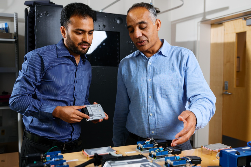
This research was led by Abbas Ali, PhD student at the University of Michigan-Dearborn, working alongside Prof. Hafiz Malik in the Information Systems, Security, and Forensics (ISSF) Laboratory.
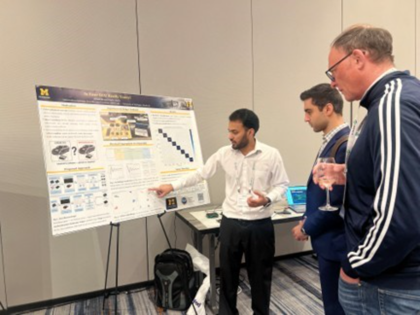
Their paper, "Short: Is Your ECU Really Yours?", was presented at the 4th USENIX Symposium on Vehicle Security and Privacy (VehicleSec 2026) in Baltimore, MD. The complete technical paper, open-access proceedings, and presentation slides are available directly on theUSENIX page. Furthermore, the paper earned all three USENIX Artifact Badges (Available, Functional, Reproduced). To support open security research, the complete dataset of 48,000 raw waveforms (2.6 GB), pre-extracted 211-D feature CSVs, pre-trained machine learning models, and Jupyter evaluation notebooks are publicly archived on Zenodo (DOI: 10.5281/zenodo.19666939).
ECU Fingerprinting & Physical-Layer Security FAQ
Why is cryptographic authentication insufficient for preventing ECU cloning?
Cryptography verifies that a message carries a valid signature or token, but it cannot verify the physical origin of the signal. If an attacker clones an ECU's firmware and cryptographic credentials onto counterfeit hardware, software-level checks accept the impostor as legitimate. Physical-layer fingerprinting checks the hardware itself.
Why was the Red Pitaya STEMlab 125-14 selected over traditional bench oscilloscopes?
Bench oscilloscopes sampling at 2.5 GS/s are expensive and require a tethered host workstation, making vehicle or field deployment impossible. The Red Pitaya combines 14-bit 125 MS/s ADCs with an onboard ARM processor, enabling high-resolution signal capture and real-time ML inference on a single, hand-sized board.
Does this framework require modifying ECU firmware or connecting to internal chip states?
No. The system operates completely non-invasively by probing digital lines (such as GPIO toggles or CAN bus lines) during normal operation. It requires no firmware modifications, internal SRAM reads, or custom silicon modifications.
How does the system handle differential signals like CAN_H and CAN_L?
Using the STEMlab’s two synchronized input channels, the system captures CAN_H and CAN_L simultaneously. Analyzing each line individually alongside the differential signal reveals output driver asymmetries that standard differential receivers filter out, providing richer fingerprint features.
Recent Posts
-
 October 20, 2026
-
-