
In particle accelerator facilities, the difference between a successful nuclear physics experiment and a failed run often comes down to beam bunching efficiency. While single-frequency sine wave cavities are standard, they suffer from a poor bunching efficiency of roughly 31%.
To push this efficiency to 71% and beyond, accelerator engineers turn to sawtooth waveforms. However, traditional analog sawtooth generators are bulky, rigid, and prone to component obsolescence.
This implementation, developed by Ashish Sharma, Subrat Kar, and Bhuban Kumar Sahu from the Indian Institute of Technology (IIT) Delhi and the Inter-University Accelerator Centre (IUAC), presents a compact, wideband, and fully reconfigurable embedded instrument designed to generate stable RF sawtooth waveforms. By utilizing an SoC-FPGA (System-on-Chip Field Programmable Gate Array), this design handles complex signal processing and feedback control in a single hardware footprint.
The Physics of the Sawtooth: Multi-Harmonic Synthesis
A perfect sawtooth waveform consists of a long linear ramp followed by a near-instantaneous fall time. In the RF regime, this is approximated by combining multiple sub-harmonics—specifically the first, second, and third harmonics—with precise amplitude and phase control.
The proposed system regulates and combines three signals (typically 12.125, 24.25, and 36.375 MHz) to drive a Multi-Harmonic Buncher (MHB). The resulting waveform translates to:
- x(t) = A₀ cos(ω₀t + φ₀) + A₁ cos(2ω₀t + φ₁) + A₂ cos(3ω₀t + φ₂)
- Independent control over the amplitude (Aₙ) and phase (φₙ) of each harmonic.
- Deterministic timing achieved by hosting the entire control logic within the FPGA fabric.

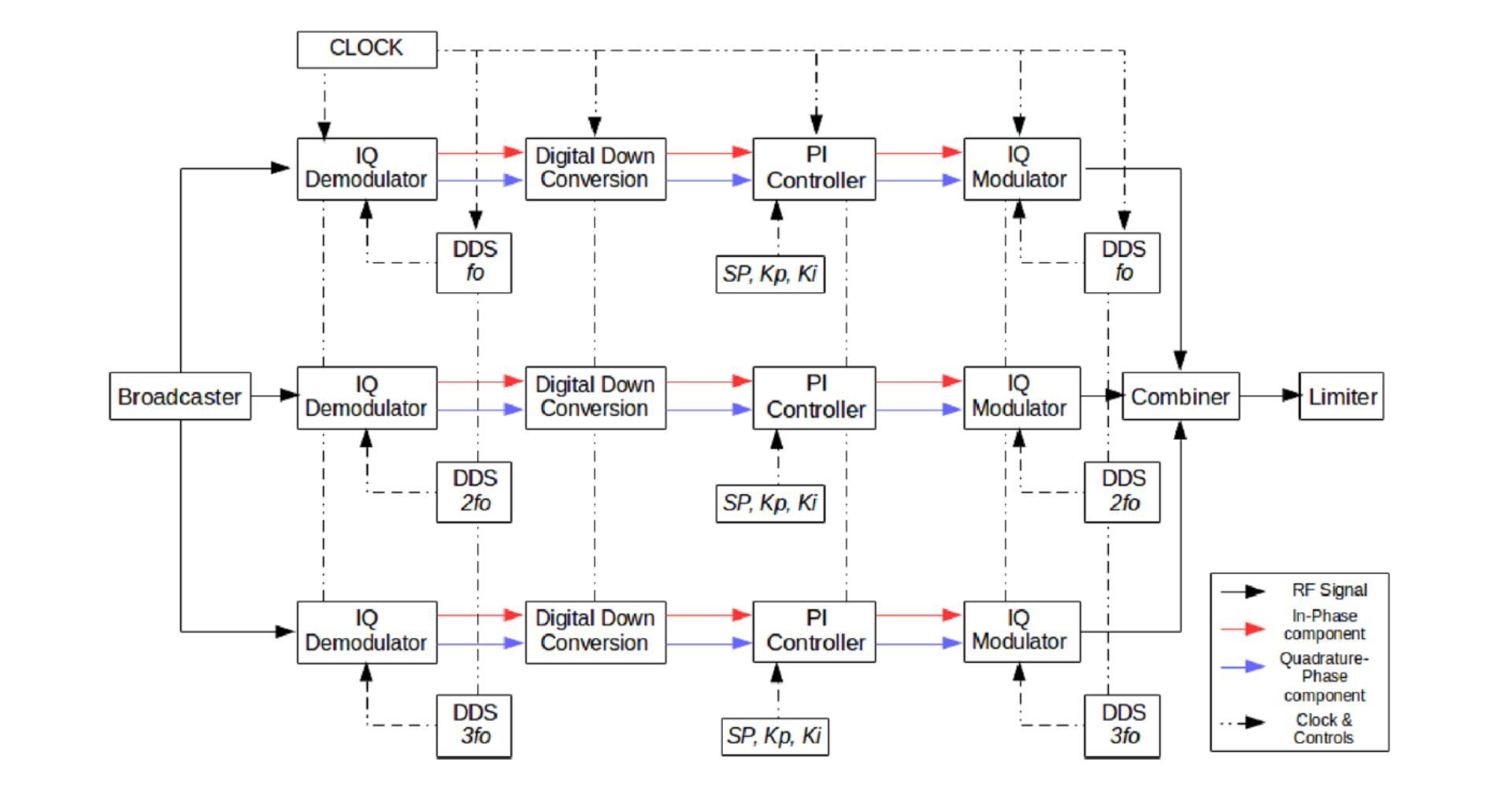
Overall block design of the proposed RF sawtooth generator instrument
Architecture: FPGA-Driven IQ Control
Unlike previous digital designs that required fixed, difficult-to-source sampling clocks, this architecture uses a commercial Si5356-based fractional PLL multiplier. This allows the 125 MHz system clock to synchronize with any external reference signal, providing unprecedented frequency agility.
Digital Down-Conversion (DDC) and Filtering
To stabilize the beam, the feedback signal from the RF cavities is processed through parallel chains:
- IQ Demodulation: The high-frequency feedback is product-modulated into In-Phase (I) and Quadrature-Phase (Q) baseband components.
- Resource-Optimized Filtering: Instead of computationally heavy high-cutoff FIR filters, the system employs Cascaded-Integrator Comb (CIC) decimation filters. These downsample the rate from 125 MHz to 1.25 MHz, saving vital FPGA DSP resources.
- Digital PI Control: Six independent Proportional-Integral (PI) loops regulate the IQ components, eliminating steady-state error without the latency of CORDIC-based amplitude/phase conversions.

FPGA algorithm block design showing internal signal processing chains
Remote Operation and "Networked" Hardware
For modern accelerator labs, manual tuning at a rack is no longer practical. This instrument runs a TCP/IP-based server directly on the ARM processor part of the SoC-FPGA.
Engineers can interface with the device using a Python Qt-based GUI, allowing for:
- Real-time gain tuning and set-point adjustments.
- Integrator RESET switches to activate/deactivate control loops on the fly.
- Remote monitoring over Ethernet, suitable for large-scale facilities like the Pelletron or High-Current Injector accelerators at IUAC.

Python Qt-based graphical user interface for remote control
FAQ: RF Sawtooth Generation & Particle Accelerators
Why is a sawtooth waveform better than a sine wave for beam bunching?
A sine wave only provides linear velocity modulation for a small fraction of the beam, leading to poor bunching efficiency (~31%). A sawtooth waveform’s linear ramp acts on a larger portion of the continuous ion beam, significantly increasing the efficiency to approximately 71% by ensuring more particles arrive at the focus point simultaneously.
What are the advantages of using an SoC-FPGA over traditional analog electronics?
Analog systems are bulky and frequency-selective, meaning you need different hardware for different experimental frequencies. The SoC-FPGA approach is reconfigurable via software, handles all feedback loops digitally (avoiding component drift), and is compact enough to fit into a standard 19-inch rack-mountable box.
How does the system maintain phase stability across different harmonics?
The system uses Digital Down-Conversion (DDC) to extract baseband IQ components. By regulating the I and Q components simultaneously through PI controllers, the loop inherently maintains phase synchronization ($2n\pi$) without needing external analog phase rotators.
Is this design portable to other FPGA platforms?
Yes. While developed on the Red Pitaya STEMLab 125-14 (Xilinx Zynq 7010), the modular Verilog and AXI-interface structure make the digital signal processing (DSP) logic portable to other Xilinx or Intel FPGA platforms with appropriate ADC/DAC front-ends.
Technical Summary & Publication Credits
This research provides a cost-effective, high-performance alternative to proprietary LLRF (Low-Level RF) systems.
Key Specifications:
- FPGA Device: Xilinx Zynq 7010z (Red Pitaya 125-14)
- ADC/DAC: 14-bit, 125 MSPS (Input) / 250 MSPS (Output)
- Control Interface: AXI-based memory-mapped IO with Python backend
Authors: Ashish Sharma, Subrat Kar, and Bhuban Kumar Sahu.
Read the full research paper Compact embedded RF sawtooth waveform generator for particle accelerator applications.


