---
title: "Autonomous Sub-100ms Laser Relocking in Trapped-Ion Quantum Experiments: Scaling the BLOOD Lockbox Architecture with Red Pitaya SoCs"
description: Discover how ETH Zurich’s TIQI group built autonomous sub-100ms laser relocking into the Red Pitaya-based BLOOD lockbox for quantum optics.
image: https://content.redpitaya.com/hubfs/blog%20featured%20image%20-%202026-08-12T152830.130.jpg
---
[](https://redpitaya.com/)
[](https://redpitaya.com/)
- Products
- [STEMlab 125-14 Gen 2](https://redpitaya.com/stemlab-125-14-gen2/)
- [STEMlab 125-14](https://redpitaya.com/stemlab-125-14/)
- [SIGNALlab 250-12](https://redpitaya.com/signallab-250-12/)
- [SDRlab 122-16](https://redpitaya.com/sdrlab-122-16/)
- [STEMlab TI (Texas Instruments)](https://redpitaya.com/stemlab-ti-texas-instruments/)
- [Multi-channel Solutions](https://redpitaya.com/multi-channel-solutions/)
- [Accessories](https://redpitaya.com/accessories/)
- [Applications](https://redpitaya.com/applications/)
- Documentation
- [Technical Documentation](https://redpitaya.com/documentation/)
- [Teaching materials](https://redpitaya.com/teaching-materials/)
- [Student projects](https://redpitaya.com/student-projects/)
- [User forum](https://forum.redpitaya.com/)
- [About](https://redpitaya.com/about-us/)
- [History](https://redpitaya.com/history/)
- [Distributors](https://redpitaya.com/distibutors-red-pitaya/)
- [Blog](https://content.redpitaya.com/blog)
[Shop](https://redpitaya.com/shop/)
- [ACADEMIA](https://redpitaya.com/academia/)
- [RADIO AMATEURS](https://redpitaya.com/radio-amateurs/)
- [Home](https://redpitaya.com/)
- Products
- [STEMlab 125-10](https://redpitaya.com/stemlab-125-10/)
- [STEMlab 125-14](https://redpitaya.com/stemlab-125-14/)
- [SIGNALlab 250-12](https://redpitaya.com/signallab-250-12/)
- [SDRlab 122-16](https://redpitaya.com/sdrlab-122-16/)
- [Accessories](https://redpitaya.com/accessories/)
- [Applications](https://redpitaya.com/applications/)
- [Resources](https://redpitaya.com/documentation/)
- [Shop](https://redpitaya.com/shop/)
- [About](https://redpitaya.com/about-us/)
- [Blog](https://content.redpitaya.com/blog)
- [Compare](https://redpitaya.com/compare/)
- [Login / Register](https://redpitaya.com/my-account/)
### Red Pitaya Blog
[Home](https://redpitaya.com) » [Case study](https://content.redpitaya.com/blog/tag/case-study) »
[Case study](https://content.redpitaya.com/blog/tag/case-study)
# Autonomous Sub-100ms Laser Relocking in Trapped-Ion Quantum Experiments: Scaling the BLOOD Lockbox Architecture with Red Pitaya SoCs
- Posted by  [Red Pitaya Technical Editorial Team](https://redpitaya.com/Red-Pitaya-Blog-team/) , September 1, 2026
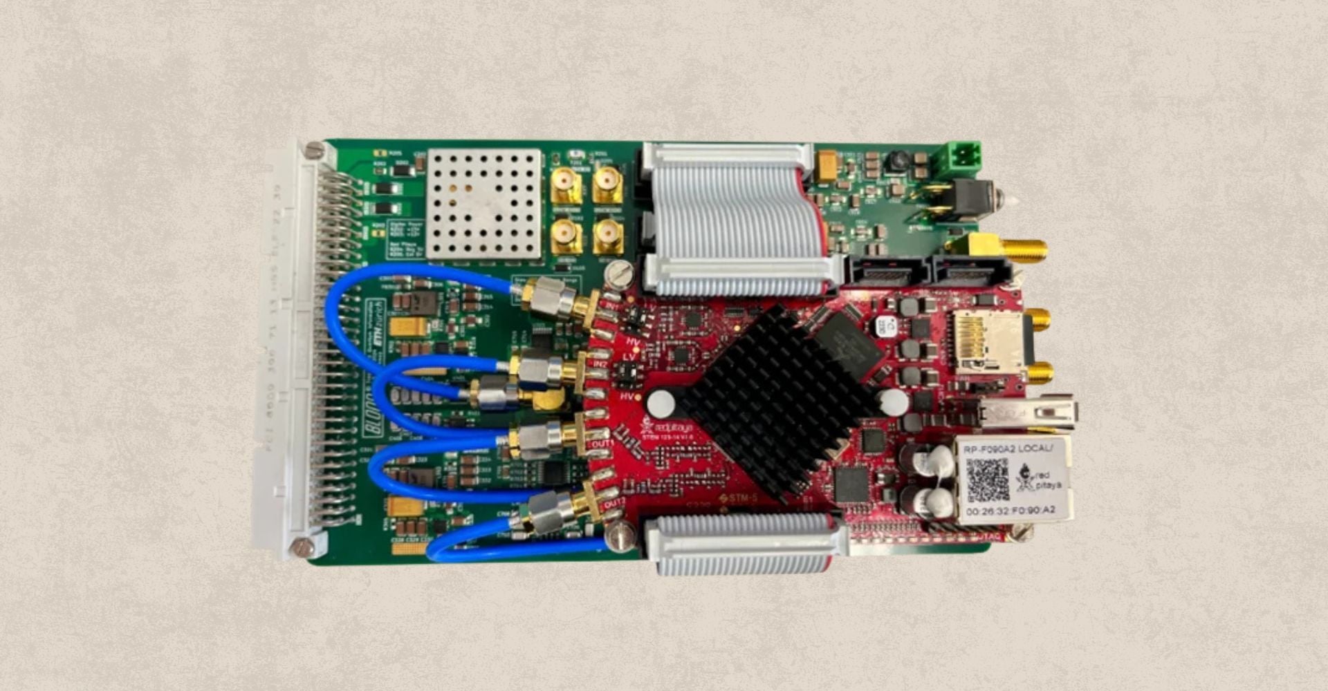
**How ETH Zurich’s Trapped Ion Quantum Information Group integrated on-chip XADC sensing and dynamic FPGA sweep generators to achieve robust, hands-free Pound–Drever–Hall lock recovery.**
In experimental quantum optics and trapped-ion quantum computing, laser frequency stability is non-negotiable. Quantum state manipulation, gate execution, and high-fidelity ion readout demand laser light locked tightly to optical reference cavities using techniques like Pound–Drever–Hall (PDH) frequency stabilization.
However, optical cavity stability faces a persistent physical vulnerability: acoustic noise, mechanical micro-vibrations, and thermal drifts. While Proportional-Integral (PI) feedback loops correct for continuous, small-scale frequency drifts, a strong shock can push the laser frequency outside the linear range of the PDH error signal. Historically, once a controller lost lock, operators were required to manually sweep the piezo actuator, locate resonance, and re-engage feedback loops—interruptions that degraded system uptime in complex quantum computing architectures.
To solve this automation bottleneck, the **Trapped Ion Quantum Information (TIQI) Group** at **ETH Zürich** developed an autonomous relocking mechanism built directly on the [Red Pitaya STEMlab 125-14](https://www.google.com/search?q=https://redpitaya.com/product/stemlab-125-14) platform.
Implemented on BLOOD (Bichannel Lockbox On One Device), this custom PI controller enables automatic lock recovery in under 100 ms after severe disturbances, eliminating the need for manual intervention. This enhancement was initially built as a software-driven feature by researcher Daria Panfilova and subsequently migrated into the hardware fabric by supervisor Bahadır Dönmez to achieve true deterministic performance. The project was overseen by Dr. Martin Stadler and Prof. Dr. Jonathan Home.
**1. The Core Engineering Problem: The Narrow Linear Capture Window of PDH Locking**
The Pound–Drever–Hall (PDH) technique generates an antisymmetric error signal by phase-modulating laser light prior to entering a Fabry–Pérot cavity. Near resonance, the PDH error signal acts as a steep derivative curve, providing a linear response that enables PI controllers to steer the laser frequency or piezo-driven cavity mirror back to nominal zero.
[](https://content.redpitaya.com/blog/sub-100ms-automated-laser-relocking-red-pitaya-trapped-ion-quantum#_msocom_1)
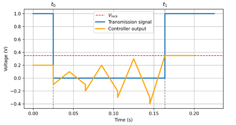
*Figure 1: Timeline showing how the controller pauses the PI loop at lock loss (t0) and initiates triangular search sweeps with stepwise-increasing amplitudes until cavity resonance is rediscovered (t1). Image credit: Daria Panfilova, ETH Zürich*
The fundamental limitation lies in the **capture range**. The linear region of a high-finesse optical cavity is narrow. When a sudden physical impact shifts the optical path length beyond this slope, the PDH error signal drops back to zero. To a standard PI controller, a zero-voltage error signal looks identical to perfect resonance. Consequently, the integral register accumulates error (windup), driving the piezo actuator to its voltage rails while the laser drifts out of lock.
**2. System Architecture: Integrating Red Pitaya’s On-Chip XADC for Dual-Path Monitoring**
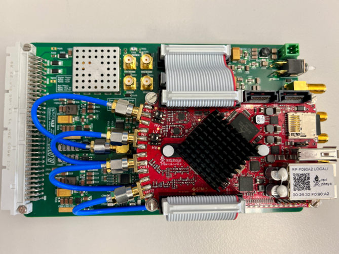
***Figure 2:** The Red Pitaya STEMlab 125-14 board mounted directly onto the custom carrier PCB with analog interface electronics used in the TIQI laboratory. Image credit: Daria Panfilova, ETH Zürich*
The BLOOD lockbox leverages the dual fast 14-bit ADC and DAC channels (125 MSps) of the Xilinx Zynq-7010 SoC on the Red Pitaya STEMlab 125-14 for its core PDH demodulation and PI feedback control loop.
To detect lock loss reliably without consuming one of the primary high-speed RF input channels, the ETH Zürich team modified the Linux device tree to access the **Zynq processor's auxiliary analog-to-digital converter (XADC)** via the Industrial I/O (IIO) subsystem.
**Dual-Signal Sensing Strategy:**
1. **Primary PDH Feedback Path:** The reflected PDH error signal enters the fast ADC (Channel 1), running through hardwired FPGA logic to generate real-time PI corrections. These corrections are sent to the primary fast piezo DAC output, while secondary drift corrections can be managed sequentially to keep the fast actuator centered within its dynamic range.
2. **Lock-Status Detection Path:** The cavity transmission signal—which exhibits a maximum voltage peak exclusively during optical resonance—is connected directly to an analog pin mapped to the Zynq’s internal XADC. In this software-driven architecture, these digitized transmission levels are routed through the Linux Industrial I/O (IIO) ring buffer to the embedded C++ server. If the cavity transmission intensity drops below a user-defined software threshold, the server logic classifies the system as "unlocked," commands the PI loop integrator to freeze to prevent windup, and initiates the localized search sweep.
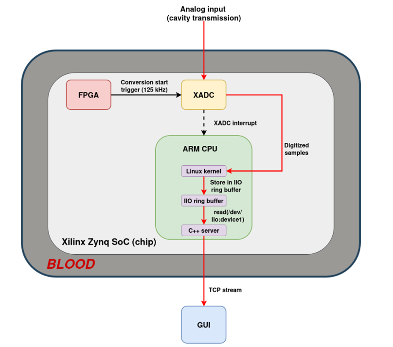
*Figure 3: Block diagram illustrating the XADC trigger, the Zynq SoC converter, the Linux Industrial I/O (IIO) ring buffer, and the C++ server data streaming pipeline. Image credit: Daria Panfilova, ETH Zürich*
By continuously sampling the transmission signal via the Zynq's auxiliary XADC, the embedded C++ server maintains a real-time monitor of optical coupling. If the transmission level drops below the user-defined software threshold, the server logic immediately classifies the system as 'unlocked,' freezes the PI loop integrator to prevent actuator windup, and initiates the relocking search sequence.
**3. The Relocking Algorithm: Hardware-Driven Dynamic Amplitude Ramping**
The core logic of the autonomous relocking system was initially developed and validated as a C++ software routine running on the Red Pitaya’s embedded Linux server. By combining software-driven control with the FPGA’s existing sweeper functionality, the system executes a structured, four-step recovery state machine:
1. **Integrator Freeze:** Upon detecting lock loss via the XADC transmission signal, the control software instantly pauses the PI loop and freezes the integrator register values. This eliminates "integrator windup," preventing the piezo actuator from slamming into its limits while off-resonance.
2. **Hardware Sweep Initialization:** The system activates the FPGA’s internal triangular wave generator, outputting a localized search sweep directly to the piezo DAC.
3. **Stepwise Amplitude Scaling:** To prevent mechanical overshoot, the search amplitude starts at a narrow baseline and systematically doubles after each acquisition cycle until the resonance is rediscovered.
4. **Fast Re-Lock:** Once a transmission peak is detected, the software calculates the exact lock point. To prevent severe voltage jumps that could cause oscillation, the output is smoothly ramped to the newly identified lock voltage before the high-speed PI feedback loop is re-engaged.
**4. Empirical Performance: Laboratory Validation on a Bow-Tie Optical Cavity**
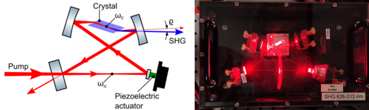

***Figure 4:** (a) Simplified optical schematic and (b) laboratory photograph of the frequency-doubling ultraviolet bow-tie cavity used to test the relocking algorithm. Image credit: Nicola Meggiato, ETH Zürich.*
The automated relocking feature was subjected to benchtop verification using simulated signals and tested in an optics lab setup operating a **frequency-doubling bow-tie cavity** equipped with a piezo actuator.
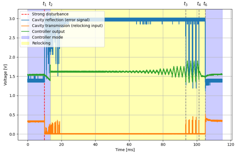
***Figure 5:** Shows the full measurement sequence (the table knock, the unlock, the search, and the re-lock). Image credit: Daria Panfilova, ETH Zürich*
**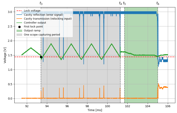**

***Figure 6:** Azoomed-in view of the relocking phase between t2 and t6. Image credit: Daria Panfilova, ETH Zürich*
**Key Performance Characteristics:**
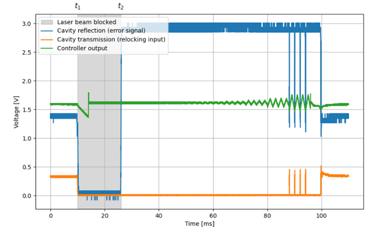
- **Relocking Latency:** Across violent physical disturbances engineered to knock the cavity out of lock (including total beam blocks), the software-driven prototype consistently re-acquired lock in under **100 ms**.
- **System Autonomy:** The PyQt graphical user interface (GUI) was expanded to display real-time XADC transmission streams alongside PDH error signals. This allows operators to observe recovery metrics and customize transmission limits without manual intervention.
- **Channel Efficiency:** By leveraging the Zynq's integrated XADC for lock monitoring, both primary fast ADC channels remain fully available for dual-channel optical control.
# 
***Figure 7:** Relocking after temporarily blocking the beam. The system detects the loss of lockand automatically relocks once the beam is restored. Image credit: Daria Panfilova, ETH Zürich*
If your optical bench requires both continuous cavity locking and nanosecond-precise pulse sequencing, check out our [Comprehensive Red Pitaya Open-Source Selector Guide](https://content.redpitaya.com/blog/open-source-experimental-control-red-pitaya-selector-guide) to see how BLOOD can be integrated into a synchronized dual-board Master/Slave architecture.
---
### Technical FAQ for Quantum Optics & Control Engineers
### **How does reading the XADC impact real-time execution and signal monitoring?**
Initially, the team routed the XADC transmission levels into the C++ Linux server over the Industrial I/O (IIO) subsystem. However, relying on software drivers created complex synchronization lag between the XADC stream and the main oscilloscope channels. To solve this, the TIQI team migrated the relocking logic directly into the FPGA and upgraded the system to a native 3-channel hardware oscilloscope. This bypasses the OS software entirely, delivering perfect, deterministic phase-locking between the transmission monitor and the PDH error signals.
### **Why use the auxiliary XADC for transmission detection instead of the second fast ADC channel?**
Using the primary fast ADCs (125 MSps, 14-bit) for low-frequency amplitude thresholding is an inefficient use of hardware resources. By routing the slow cavity transmission detector to the processor's internal XADC—operating at a fixed 31.25 kHz per channel (derived from a 125 kHz conversion trigger divided across four enabled analog inputs)—the STEMlab 125-14 preserves its second high-speed RF input for secondary fast channels, such as a second laser lock path or intensity stabilization loop (hence Bichannel Lockbox On One Device).
### **How does the system prevent false relocking triggers during normal experimental phase fluctuations?**
Lock-loss detection relies on strict user-defined upper and lower voltage limits applied to the cavity transmission signal. Through the custom graphical user interface (GUI), operators can visually monitor the real-time XADC transmission stream and fine-tune these thresholds to fit the specific noise floor of their bench, ensuring the sweep generator only triggers during a true lock-loss event.
### About the Red Pitaya Team
The Red Pitaya Technical Editorial Team is a cross-functional group of technical communicators and product specialists. By synthesizing insights from our hardware developers and global research partners, we provide verified, high-value content that bridges the gap between open-source innovation and industrial-grade precision.
Our mission is to make advanced instrumentation accessible to engineers, researchers, and educators worldwide.
##### Categories
- [academia (47)](https://content.redpitaya.com/blog/tag/academia)
##### Recent Posts
- [](https://content.redpitaya.com/blog/non-invasive-gerd-detection-radiofrequency-spectrophotometry)
[Non-Invasive GERD Detection: Continuous Esophageal Monitoring via Radiofrequency Spectrophotometry](https://content.redpitaya.com/blog/non-invasive-gerd-detection-radiofrequency-spectrophotometry)
September 29, 2026
- [](https://content.redpitaya.com/blog/open-source-mri-console-ocra-marcos-red-pitaya)
[How a $500 Open-Source MRI Console Sparked a Global Research Ecosystem](https://content.redpitaya.com/blog/open-source-mri-console-ocra-marcos-red-pitaya)
September 22, 2026
- [](https://content.redpitaya.com/blog/zephyr-rtos-nordic-logic-analyzer-workshop-eestec-ljubljana)
[Probing the Wire: Red Pitaya & Zephyr RTOS Workshop with EESTEC](https://content.redpitaya.com/blog/zephyr-rtos-nordic-logic-analyzer-workshop-eestec-ljubljana)
September 17, 2026
##### Subscribe to our newsletter

An open-source solution for hobbyists, professors,
radio amateurs and industrial clients.
**Red Pitaya**
Velika pot 21,
5250 Solkan
Slovenia, Europe
Phone: +386 30 322 719
Email: [info@redpitaya.com](mailto:info@redpitaya.com)
**Red Pitaya US**
TX, Dallas - Downtown Republic Center
325 N. St. Paul Street
Suite 3100
Dallas, Texas, 75202
United States of America
IMPORTANT: This address does not accept RMAs
Phone: (888) 637-2706
Email: [US.office@redpitaya.com](mailto:US.office@redpitaya.com)
- Customer Service
- [Customer Support](https://redpitaya.com/customer-support/)
- [Shipping & Returns](https://redpitaya.com/shipping-returns/)
- [Contact us](https://redpitaya.com/contact-us/)
- [Cookie Policy](https://redpitaya.com/cookie-policy/)
- SLO
- [O nas](https://redpitaya.com/o-nas/)
- [Pogoji poslovanja](https://redpitaya.com/pogoji-poslovanja/)
- [Politika zasebnosti](https://redpitaya.com/politika-zasebnosti/)
- [Politika piškotkov](https://redpitaya.com/politika-piskotkov/)
##### Follow Us
#### Subscribe to our newsletter
Get notified about new SW features & updates, news about latest community projects & events and new Red Pitaya products & discounts
[Subscribe](https://go.redpitaya.com/cs/c/?cta_guid=36ccbdc0-0344-49c4-aa91-aa67cf437c09&signature=AAH58kHkxFYTAKU-ILQzHI1jlrdI_co0RA&placement_guid=a24cb732-1dfb-4d0a-8c52-aa6851ce9102&click=556cfaee-eee4-48e4-95e7-c483a4f78883&hsutk=537e15e740555d2fd6a1c1ad931d2b6f&canon=https%3A%2F%2Fredpitaya.com%2Fabout-us%2F&utm_referrer=https%3A%2F%2Fredpitaya.com%2Fcompare%2F&portal_id=7715357&redirect_url=APefjpGj5Dm9poAAzHFGh4S6pJ-2TvNzBdwZZlfbr7toxfw-epFUtzEHOKToHx0i2TYYr39srj9aSERdntJBh8lJqoSXL-pUF2gwhYvOW6IMm28hQVmhYML2AIbbIRrr3YaoyJkZQ0iRxq-uHlFt66i3_8XpQpXT_M2zF9fS7t0f6hlBjGBJ7X_aXDrhBwXcEAqwoWWleG4uxonSGOR-BBp3tpKcySXYELTGHeGn5Yo61r3xrFvqFP5P6BxVwxTi51_ceW9uBzOMvA1rYz4BsIhLSF8n4bhcHqJTvhibH_laJrjDNdEUUrU&__hstc=72355340.537e15e740555d2fd6a1c1ad931d2b6f.1635738083317.1635738083317.1635746314170.2&__hssc=72355340.5.1635746314170&__hsfp=530052575&contentType=standard-page)
**Red Pitaya** 2025 All Rights Reserved.
- [Privacy Policy](https://redpitaya.com/privacy-policy/)
- [Terms of Use](https://redpitaya.com/terms-of-use/)
```json
{
"@context" : "https://schema.org",
"@type" : "BlogPosting",
"author" : {
"@type" : "Person",
"name" : "Red Pitaya Technical Editorial Team",
"url" : "https://content.redpitaya.com/blog/author/red-pitaya-technical-editorial-team"
},
"dateModified" : "2026-09-01T08:30:00.024Z",
"datePublished" : "2026-09-01T08:30:00.000Z",
"headline" : "Autonomous Sub-100ms Laser Relocking in Trapped-Ion Quantum Experiments: Scaling the BLOOD Lockbox Architecture with Red Pitaya SoCs",
"image" : [ "https://content.redpitaya.com/hubfs/blog%20featured%20image%20-%202026-08-12T152830.130.jpg" ],
"mainEntityOfPage" : {
"@id" : "https://content.redpitaya.com/blog/sub-100ms-automated-laser-relocking-red-pitaya-trapped-ion-quantum",
"@type" : "WebPage"
},
"publisher" : {
"@type" : "Organization",
"logo" : {
"@type" : "ImageObject",
"url" : "https://content.redpitaya.com/hubfs/Red-pitaya-logo.jpg"
},
"name" : "Red Pitaya d.o.o."
}
}
```