---
title: How a $500 Open-Source MRI Console Sparked a Global Research Ecosystem
description: How MIT, OVGU Magdeburg, and the MaRCoS community evolved OCRA into an open-source low-field MRI control ecosystem built around Red Pitaya hardware.
image: https://content.redpitaya.com/hubfs/blog%20featured%20image%20-%202026-09-17T131400.982-3.jpg
---
[](https://redpitaya.com/)
[](https://redpitaya.com/)
- Products
- [STEMlab 125-14 Gen 2](https://redpitaya.com/stemlab-125-14-gen2/)
- [STEMlab 125-14](https://redpitaya.com/stemlab-125-14/)
- [SIGNALlab 250-12](https://redpitaya.com/signallab-250-12/)
- [SDRlab 122-16](https://redpitaya.com/sdrlab-122-16/)
- [STEMlab TI (Texas Instruments)](https://redpitaya.com/stemlab-ti-texas-instruments/)
- [Multi-channel Solutions](https://redpitaya.com/multi-channel-solutions/)
- [Accessories](https://redpitaya.com/accessories/)
- [Applications](https://redpitaya.com/applications/)
- Documentation
- [Technical Documentation](https://redpitaya.com/documentation/)
- [Teaching materials](https://redpitaya.com/teaching-materials/)
- [Student projects](https://redpitaya.com/student-projects/)
- [User forum](https://forum.redpitaya.com/)
- [About](https://redpitaya.com/about-us/)
- [History](https://redpitaya.com/history/)
- [Distributors](https://redpitaya.com/distibutors-red-pitaya/)
- [Blog](https://content.redpitaya.com/blog)
[Shop](https://redpitaya.com/shop/)
- [ACADEMIA](https://redpitaya.com/academia/)
- [RADIO AMATEURS](https://redpitaya.com/radio-amateurs/)
- [Home](https://redpitaya.com/)
- Products
- [STEMlab 125-10](https://redpitaya.com/stemlab-125-10/)
- [STEMlab 125-14](https://redpitaya.com/stemlab-125-14/)
- [SIGNALlab 250-12](https://redpitaya.com/signallab-250-12/)
- [SDRlab 122-16](https://redpitaya.com/sdrlab-122-16/)
- [Accessories](https://redpitaya.com/accessories/)
- [Applications](https://redpitaya.com/applications/)
- [Resources](https://redpitaya.com/documentation/)
- [Shop](https://redpitaya.com/shop/)
- [About](https://redpitaya.com/about-us/)
- [Blog](https://content.redpitaya.com/blog)
- [Compare](https://redpitaya.com/compare/)
- [Login / Register](https://redpitaya.com/my-account/)
### Red Pitaya Blog
[Home](https://redpitaya.com) » [Amateur Radio](https://content.redpitaya.com/blog/tag/amateur-radio), [Blog](https://content.redpitaya.com/blog/tag/blog), [Academia](https://content.redpitaya.com/blog/tag/academia), [Case study](https://content.redpitaya.com/blog/tag/case-study) »
[Amateur Radio](https://content.redpitaya.com/blog/tag/amateur-radio), [Blog](https://content.redpitaya.com/blog/tag/blog), [Academia](https://content.redpitaya.com/blog/tag/academia), [Case study](https://content.redpitaya.com/blog/tag/case-study)
# How a $500 Open-Source MRI Console Sparked a Global Research Ecosystem
- Posted by  [Red Pitaya Technical Editorial Team](https://redpitaya.com/Red-Pitaya-Blog-team/) , September 22, 2026
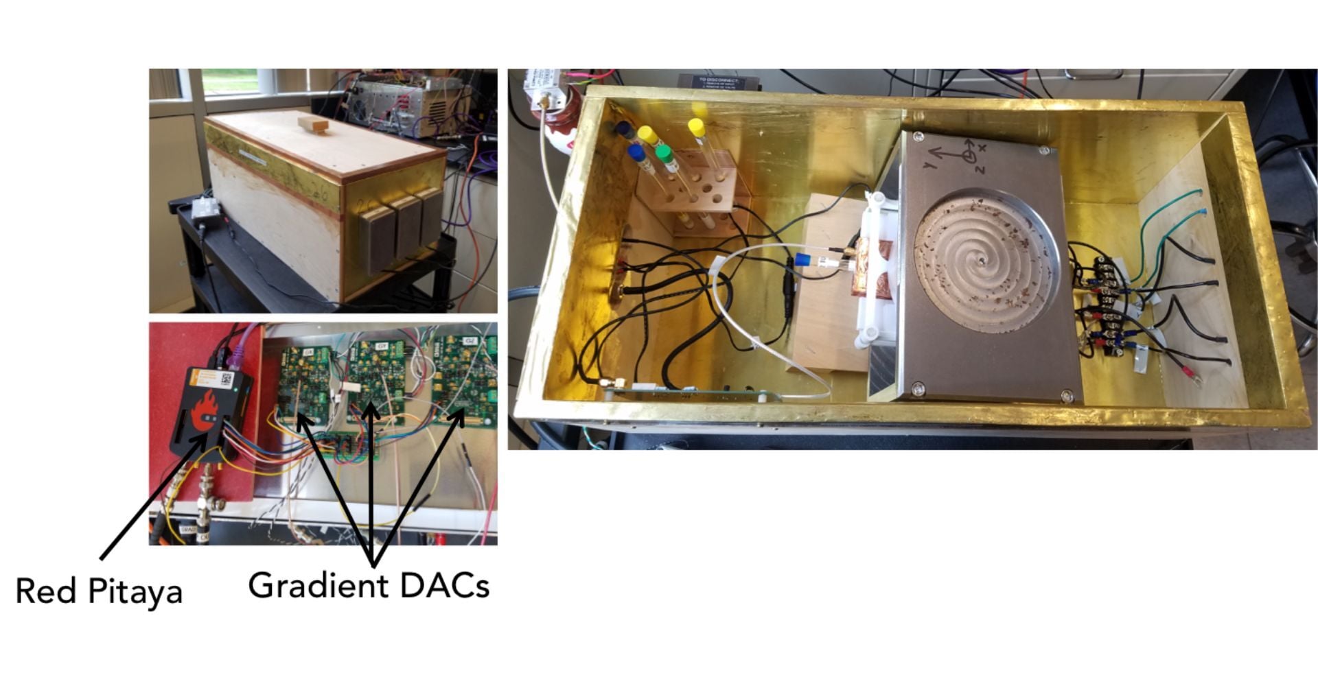
## **From MIT Classroom Tabletop to MaRCoS and Clinical-Style Low-Field MRI Workflows**
Conventional Magnetic Resonance Imaging (MRI) consoles are expensive, closed systems. Proprietary spectrometer architectures, locked pulse-sequence compilers, and restrictive software interfaces make it difficult for students and researchers to inspect signal paths, modify low-level control loops, or build accessible scanners for education and low-field research.
In 2018, researchers at the Athinoula A. Martinos Center for Biomedical Imaging (Massachusetts General Hospital / MIT) addressed this barrier by developing OCRA (*Open-source Console for Real-time Acquisition*). Proving that an open console could be built from commercially available hardware, the team demonstrated imaging on a ~0.4 T educational tabletop MRI scanner using less than $500 in essential console electronics.
**Key Takeaways**
- **Democratizing Low-Field MRI:** Developed at MIT/MGH, OCRA proved that an open-source, sub-$500 console could replace expensive, closed MRI spectrometers using off-the-shelf components like the Red Pitaya STEMlab 125-14.
- **Hands-On Educational Platform:** The development of the OCRA1 shield enabled students at OVGU Magdeburg to build and program custom MRI hardware, bridging classroom theory and practical system engineering.
- **High-Performance Architecture:** By leveraging the Xilinx Zynq SoC, the system splits real-time tasks (7 ns timing granularity, IQ modulation/demodulation on FPGA) from high-level sequence management (embedded Linux on ARM CPU).
- **Evolution to MaRCoS:** Moving to the Red Pitaya SDRlab 122-16 upgraded the system with 16-bit ADCs, a streaming architecture for arbitrary sequence lengths, and native support for hardware-independent Pulseq files via PyPulseq.
- **Clinical-Style Interface:** The addition of MaRGE provides a user-friendly GUI featuring protocol management, DICOM export, and real-time reconstruction—enabling deployment on fieldable, low-field scanners in hospital environments.
## **The Hardware Setup: Off-the-Shelf Architecture**
Rather than treating the console as a proprietary black box, OCRA transferred its critical control functions onto accessible, commercial components:
- **RF Transceiver & Compute Core:** A Red Pitaya STEMlab 125-14 built around a **Xilinx Zynq-7010 SoC**, featuring onboard 14-bit ADCs and DACs for RF transmit and receive.
- **Gradient Control:** Three external 18-bit precision DACs (Analog Devices AD5780) driven via high-speed digital lines from the FPGA expansion header, providing the three primary gradient channels (Gx, Gy, Gz)
- **Analog Conditioning:** Basic external RF preamplification and programmable step attenuators conditioned the received NMR signal before digitization.
## **Signal Flow & Heterogeneous Architecture**
The core technical strength of OCRA was leveraging the Zynq SoC's heterogeneous architecture, pairing hardware determinism with flexible software control:
- **FPGA Programmable Logic (PL):** Executed pulse sequences in hard real time with approximately 7 ns timing granularity. The FPGA fabric handled Numerically Controlled Oscillator (NCO) digital mixing, digital IQ modulation and demodulation, and Direct Memory Access (DMA) streaming for transmit, receive, and gradient channels independent of CPU scheduling delays.
- **ARM Processing System (PS):** Ran an embedded Linux environment, handling sequence coordination and communicating asynchronously with an external host computer over Ethernet.
This architecture allowed RF pulses, gradient waveforms, and sequence timing to be updated just microseconds before execution, avoiding the constraints of static, precompiled experiments.
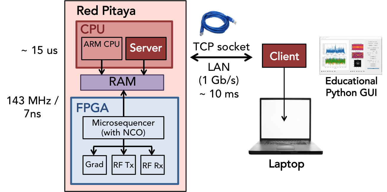
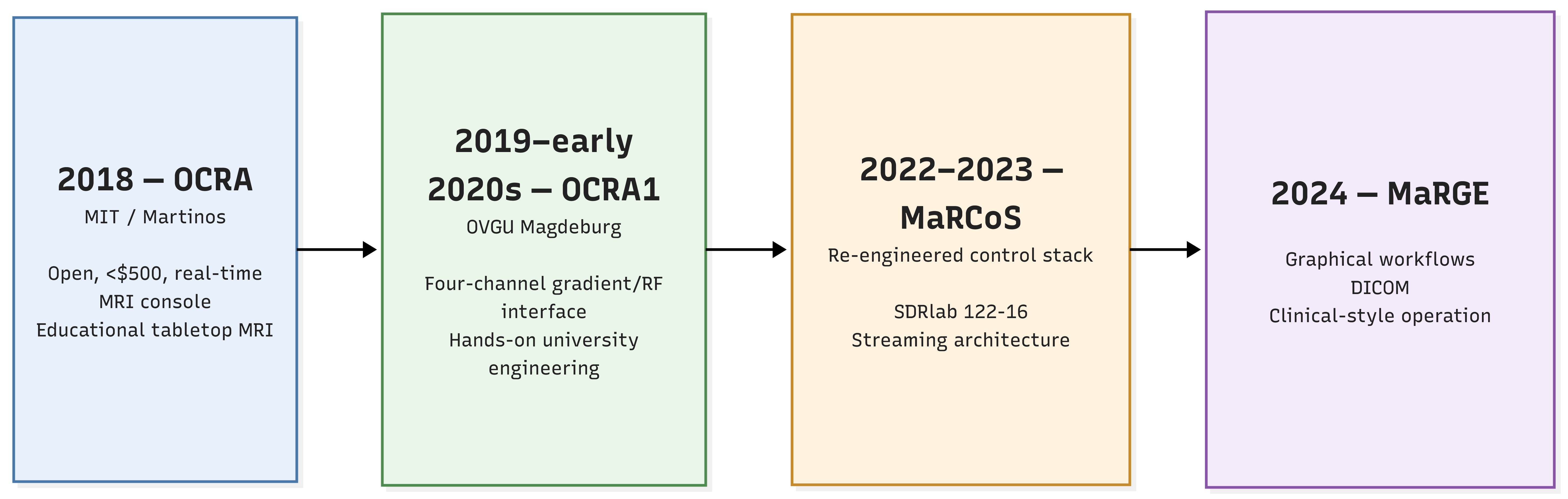
*Image 2: OCRA to MaRGE timeline. Source: Red Pitaya.*
## **From Open Console to Student-Built Hardware: The OCRA1 Shield**
OCRA's low-cost and open architecture also made it well suited to education. OCRA was developed for the MGH/MIT tabletop MRI scanners, which are used in MIT classes to teach students about MRI. Its Python-based GUI was explicitly intended as an educational tool, giving students a way to interact with and learn from the underlying MRI system.
That combination of accessible hardware and hands-on experimentation continued at Otto von Guericke University (OVGU) Magdeburg and the STIMULATE research center. Between 2019 and the early 2020s, OCRA became part of hands-on MR system engineering education, where students could work with the hardware rather than simply operate a finished imaging system.
To make that work more accessible at the benchtop, the Magdeburg team developed the **OCRA1 peripheral shield**, mounting directly onto the Red Pitaya extension headers:
- **Four-Channel Gradient DAC:** Four 18-bit AD5781B DAC channels for primary X, Y, and Z gradients, with a fourth channel available for higher-order shimming or, in appropriate systems, B0 control.
- **Integrated RF Interfacing:** Onboard RF attenuation and transmit-gate circuitry for interfacing with the RF transmit chain.
Integrated into OVGU’s *MR System Engineering* course, the shield turned the open console into a teaching platform: students could assemble hardware, characterize its behavior, program the control system, and see how their changes affected an actual MRI experiment. Instead of treating the scanner as a finished instrument, they could study and modify the individual building blocks that made the system work.
That educational use also illustrates an important part of OCRA’s evolution. Its open hardware and software made the underlying instrumentation accessible enough to be incorporated into hands-on engineering education.
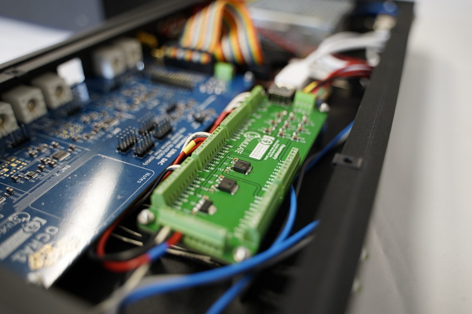
*Image 3: Red Pitaya, OCRA1 and a power-supply/distributor in a 19” case. Credit: Marcus Prier*
## **The Architectural Rewrite: MaRCoS**
As researchers began demanding longer and more complex experiments, limitations in OCRA's sequence length, timing flexibility, and assembly-style programming interface became apparent.
An international collaboration then took the OCRA approach further with **MaRCoS** (MAgnetic Resonance COntrol System), a ground-up re-engineering of the MRI control stack. While moving the main control platform to the Red Pitaya SDRlab 122-16, MaRCoS retained compatibility with the OCRA1 four-channel gradient hardware alongside newer gradient interfaces:
- **Hardware Migration to SDRlab 122-16:** MaRCoS moved to the **Red Pitaya SDRlab 122-16**, featuring 16-bit ADCs and a 122.88 MS/s sampling rate. Its ~50 MHz of usable bandwidth covers the proton Larmor frequencies encountered in low-field MRI up to roughly 1.17 T.
- **Streaming Architecture:** Sequence and acquisition data are streamed to and from the FPGA, allowing sequences of arbitrary length rather than relying on a fixed sequence-memory limit. MaRCoS uses a MessagePack-based protocol for communication between software components.
- **Pulseq Compatibility:** MaRCoS supports Pulseq-compatible sequence programming, including workflows using PyPulseq. This enables researchers to develop hardware-independent sequences in Python or MATLAB and execute them directly through the MaRCoS stack.
Want a deeper look at the MaRCoS hardware architecture?
Read the companion technical feature: [MaRCoS: An Open-Source MRI Control System Built with Red Pitaya SDRlab 122-16.](https://content.redpitaya.com/blog/open-source-mri-control-system-sdrlab/)
## **From Research Console to Clinical-Style Workflows: MaRGE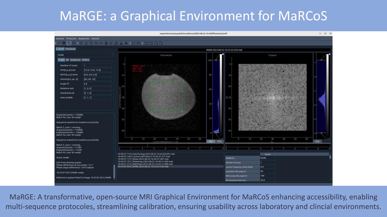**
In 2024, the consortium published **MaRGE** (*MaRCoS Graphical Environment*), providing a user-oriented interface tailored for clinical-style workflows—including protocol management, DICOM export, and integrated reconstruction tools.
The MaRCoS/MaRGE platform has been demonstrated across diverse experimental systems, including:
- An experimental 0.2 T scanner designed for hard-tissue imaging.
- A 72 mT portable scanner installed in the radiology department of a large hospital.

*Image 4: MaRGE: A graphical environment for MaRCoS. Credit: [https://www.sciencedirect.com/science/article/pii/S1090780724000466](https://www.sciencedirect.com/science/article/pii/S1090780724000466)*
- MaRCoS Control System on GitHub — [https://github.com/marcos-mri/marcos\_server](https://github.com/marcos-mri/marcos_server)
Embedded server for the MaRCoS system.
- MaRGE GUI Repository — [https://github.com/josalggui/MaRGE](https://github.com/josalggui/MaRGE)
Clinical protocol management and DICOM interface.
- Red Pitaya SDRlab 122-16 Technical Documentation — [https://redpitaya.readthedocs.io/](https://redpitaya.readthedocs.io/)
Schematics and hardware specifications.
- Red Pitaya Academia Program — [https://redpitaya.com/academia](https://redpitaya.com/academia)
University lab support and hardware sponsorships.
## **Technical FAQ**
### **Why use external DACs for gradient generation instead of the Red Pitaya’s onboard converters?**
OCRA and OCRA1 use external 18-bit DACs (AD5780/AD5781B) for gradient generation, while the Red Pitaya’s high-speed onboard converters handle the RF transmit and receive paths. The external DACs provide the precision and analog output characteristics needed by the gradient-control chain, while the onboard high-speed converters are used for RF signal processing.
### **What makes MaRCoS different from OCRA?**
MaRCoS represents a ground-up re-engineering rather than a simple software update: it changes how MRI sequences are represented, transferred, and executed. Its streaming architecture and Pulseq compatibility support sequences of arbitrary length while reducing the memory and assembly-level programming constraints of the original OCRA design.
### **Can MaRCoS run on the original STEMlab 125-14?**
The MaRCoS project is primarily designed around the SDRlab 122-16, but community documentation notes that it could be ported to the STEMlab 125-14 with reduced receive FIFO depth. The SDRlab remains the primary hardware target because of its larger FPGA resource capacity and 16-bit ADC resolution.
### About the Red Pitaya Team
The Red Pitaya Technical Editorial Team is a cross-functional group of technical communicators and product specialists. By synthesizing insights from our hardware developers and global research partners, we provide verified, high-value content that bridges the gap between open-source innovation and industrial-grade precision.
Our mission is to make advanced instrumentation accessible to engineers, researchers, and educators worldwide.
##### Categories
- [academia (47)](https://content.redpitaya.com/blog/tag/academia)
##### Recent Posts
- [](https://content.redpitaya.com/blog/non-invasive-gerd-detection-radiofrequency-spectrophotometry)
[Non-Invasive GERD Detection: Continuous Esophageal Monitoring via Radiofrequency Spectrophotometry](https://content.redpitaya.com/blog/non-invasive-gerd-detection-radiofrequency-spectrophotometry)
September 29, 2026
- [](https://content.redpitaya.com/blog/zephyr-rtos-nordic-logic-analyzer-workshop-eestec-ljubljana)
[Probing the Wire: Red Pitaya & Zephyr RTOS Workshop with EESTEC](https://content.redpitaya.com/blog/zephyr-rtos-nordic-logic-analyzer-workshop-eestec-ljubljana)
September 17, 2026
- [](https://content.redpitaya.com/blog/open-source-mri-control-system-sdrlab/)
[MaRCoS: An Open-Source MRI Control System Built with Red Pitaya SDRlab 122-16](https://content.redpitaya.com/blog/open-source-mri-control-system-sdrlab/)
September 15, 2026
##### Subscribe to our newsletter

An open-source solution for hobbyists, professors,
radio amateurs and industrial clients.
**Red Pitaya**
Velika pot 21,
5250 Solkan
Slovenia, Europe
Phone: +386 30 322 719
Email: [info@redpitaya.com](mailto:info@redpitaya.com)
**Red Pitaya US**
TX, Dallas - Downtown Republic Center
325 N. St. Paul Street
Suite 3100
Dallas, Texas, 75202
United States of America
IMPORTANT: This address does not accept RMAs
Phone: (888) 637-2706
Email: [US.office@redpitaya.com](mailto:US.office@redpitaya.com)
- Customer Service
- [Customer Support](https://redpitaya.com/customer-support/)
- [Shipping & Returns](https://redpitaya.com/shipping-returns/)
- [Contact us](https://redpitaya.com/contact-us/)
- [Cookie Policy](https://redpitaya.com/cookie-policy/)
- SLO
- [O nas](https://redpitaya.com/o-nas/)
- [Pogoji poslovanja](https://redpitaya.com/pogoji-poslovanja/)
- [Politika zasebnosti](https://redpitaya.com/politika-zasebnosti/)
- [Politika piškotkov](https://redpitaya.com/politika-piskotkov/)
##### Follow Us
#### Subscribe to our newsletter
Get notified about new SW features & updates, news about latest community projects & events and new Red Pitaya products & discounts
[Subscribe](https://go.redpitaya.com/cs/c/?cta_guid=36ccbdc0-0344-49c4-aa91-aa67cf437c09&signature=AAH58kHkxFYTAKU-ILQzHI1jlrdI_co0RA&placement_guid=a24cb732-1dfb-4d0a-8c52-aa6851ce9102&click=556cfaee-eee4-48e4-95e7-c483a4f78883&hsutk=537e15e740555d2fd6a1c1ad931d2b6f&canon=https%3A%2F%2Fredpitaya.com%2Fabout-us%2F&utm_referrer=https%3A%2F%2Fredpitaya.com%2Fcompare%2F&portal_id=7715357&redirect_url=APefjpGj5Dm9poAAzHFGh4S6pJ-2TvNzBdwZZlfbr7toxfw-epFUtzEHOKToHx0i2TYYr39srj9aSERdntJBh8lJqoSXL-pUF2gwhYvOW6IMm28hQVmhYML2AIbbIRrr3YaoyJkZQ0iRxq-uHlFt66i3_8XpQpXT_M2zF9fS7t0f6hlBjGBJ7X_aXDrhBwXcEAqwoWWleG4uxonSGOR-BBp3tpKcySXYELTGHeGn5Yo61r3xrFvqFP5P6BxVwxTi51_ceW9uBzOMvA1rYz4BsIhLSF8n4bhcHqJTvhibH_laJrjDNdEUUrU&__hstc=72355340.537e15e740555d2fd6a1c1ad931d2b6f.1635738083317.1635738083317.1635746314170.2&__hssc=72355340.5.1635746314170&__hsfp=530052575&contentType=standard-page)
**Red Pitaya** 2025 All Rights Reserved.
- [Privacy Policy](https://redpitaya.com/privacy-policy/)
- [Terms of Use](https://redpitaya.com/terms-of-use/)
```json
{
"@context" : "https://schema.org",
"@type" : "BlogPosting",
"author" : {
"@type" : "Person",
"name" : "Red Pitaya Technical Editorial Team",
"url" : "https://content.redpitaya.com/blog/author/red-pitaya-technical-editorial-team"
},
"dateModified" : "2026-09-22T08:15:01.125Z",
"datePublished" : "2026-09-22T08:15:01.000Z",
"headline" : "How a $500 Open-Source MRI Console Sparked a Global Research Ecosystem",
"image" : [ "https://content.redpitaya.com/hubfs/blog%20featured%20image%20-%202026-09-17T131400.982-3.jpg" ],
"mainEntityOfPage" : {
"@id" : "https://content.redpitaya.com/blog/open-source-mri-console-ocra-marcos-red-pitaya",
"@type" : "WebPage"
},
"publisher" : {
"@type" : "Organization",
"logo" : {
"@type" : "ImageObject",
"url" : "https://content.redpitaya.com/hubfs/Red-pitaya-logo.jpg"
},
"name" : "Red Pitaya d.o.o."
}
}
```